Fabrication drawings guide fabricators and shop floor engineers during machining. Compromising accuracy on drawings means compromising accuracy in fabrication. We bring you 4 tips to ensure accuracy in drawings to stay on course with project cost and deadlines.
Leading CAD Outsourcing Company offers solutions of Engineering CAD Services, Design Drafting & 3D Modeling
Email us:
info@truecadd.com
info@truecadd.com
Leading CAD Outsourcing Company offers solutions of Engineering CAD Services, Design Drafting & 3D Modeling
4 Tips to Ensure Accuracy in Fabrication Drawings
Updated on May 21st, 2026
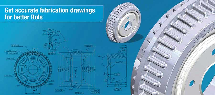
Designers and manufacturers often get carried away by the idea of getting the right product design the first time. But in reality, it involves a lot of revisions. And even after that, transferring designs into fabrication drawings involves an arduously iterative process to meet shop floor needs.
There are unavoidable conditions on shop floor such as machine tool tolerances, inherent allowances of manufacturing processes and so much more. These factors demand clear specification of allowances and geometrical dimensions in fabrication drawings to keep errors at bay and save cost and time.
The rule is simple: the higher the accuracy in drawings, the lower is the error-frequency during fabrication.
Adverse impact of inaccurate drawing details
Fabrication drawings are developed considering ideal conditions but in the real world of fabrication, there is hardly anything that is ideal. More or less every operation deviates from perfect conditions.
This deviating measurement could be as small as the 10th part of a millimeter; but cumulatively in a multi component assembly these variations result in major gaps. This is why you need fabrication drawings that accurately depict precise dimensions with accuracy in tolerances and limits and avoid any major geometrical deviations.
Research suggests that about 24% of errors in CAD drawings are related to manufacturability. If these are fixed, a lot of cost and time can be saved.
Here are 4 tips to ensure accuracy in fabrication drawings:
1. Follow “Design for Manufacturability” guidelines
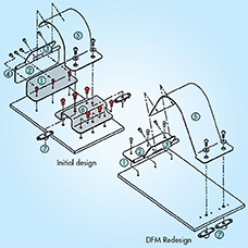
Design for Manufacturability, or simply DFM, enables design engineers to consider important factors while designing the components and guide the drafters accordingly. It tells you to assign specific tolerance for processes like punching, bending, notches, drilling etc.
For instance, the drawings specify the use of filler electrodes, direction of welding etc. using technical pre-defined symbols. In case of two consecutive welds, a pitch of 10 times the thickness of the material being welded should be maintained to avoid shunting effect or weld nuggets. There are several such thumb rules in DFM guideless for the designer.
DFM is essentially a rulebook that deals with thumb rules and exceptions for various machining processes like drilling, welding, punching, cutting, bending etc. fabrication operations. Drawings developed following DFM guidelines have lesser chances of errors and higher accuracy.
When limits and tolerances are specified in advance, the machine operator can make informed decisions. Adoption of DFM strategy during CAD drafting avoids iterative design, drafting and manufacturing processes which results in:
- Fewer reworks and saved time
- Reduced overheads by saving raw material
- On-time project completion and adherence to timelines
- Streamlined manufacturing operations
- Enabled part interchangeability with part standardization
- Easy accommodation of design revisions and ECOs
CAD drafters at TrueCADD create drawings for metal canopies and sheet metal enclosures with strict DFM guidelines as specified by chief design engineer on the project. This eliminates revisions and ECOs in drawings and enables manufacturers to carry out uninterrupted sheet metal fabrication.
Reduce interruptions with detailed fabrication drawings
2. Arranging the views for clear design communication
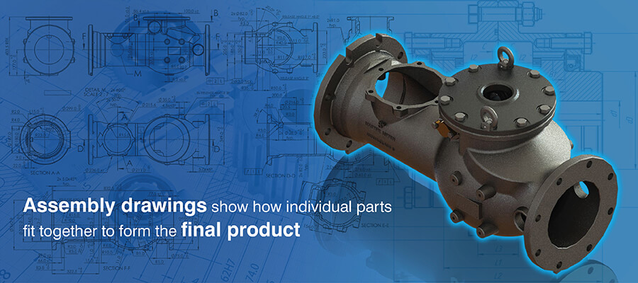
When CAD drafters develop fabrication drawings, they create quite a few views for the shop floor engineers, leaving no room for guesswork. A fabrication drawing illustrates different perspectives of a component using views to describe all the features of the component, orientation in space and with respect to the assembly’s center of gravity.
Out of all the views used, following three are the most comprehensive and communicate detailed design intent:
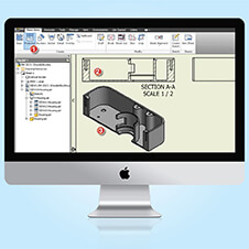
Sectional / cross-sectional view
Sectional views are the drawings made by taking a cross-section of a component or an assembly and drawn by looking at it from a plane perpendicular to the cross-section. They are especially useful during fabrication operations as they depict interior details that are otherwise shown with hidden lines and involves a lot of assumption.
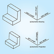
Axonometric views
An axonometric view, a pictorial drawing without dimensions, [to avoid clutter] is used to portray the understanding of the orientation of the component. This view combined with an isometric view shows part orientation and dimension with simplified design details.
Orthographic projections
Orthographic drawings are the most intuitive representation of any part by illustrating the design and geometrical details at 90° for each view. This includes creation of three drawings, the front view or the elevation, the top view or the plan and the side views [viewed from right or left], with readily available dimensions in at least one of the drawings to keep calculations out during manufacturing.
At TrueCADD, our CAD teams follow a strict quality check process to ensure that various views generated by CAD drafters are in sync with each other. Final fabrication drawings are verified by a senior QC engineer by comparing with the input drawings before releasing for the shop floor.
Early identification of drawing errors saves big money
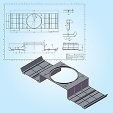
3. Avoiding excessive and overloaded details
Fabrication drawings include instructions for weldments, roller and bend tolerances, casting allowances and so much more. These are represented by symbols and hence for a large and multi-component assembly, drawings could be too overwhelming to read.
Thus, to control the information, drawings could either miss out important piece of information or could be overloaded with details. Both these are undesirable as they restrict design intent interpretation and are sent back to the drafters.
The confusion can be avoided by adding only those details that address manufacturing conditions, shop floor tooling capabilities, intent of product etc.
For example, our CAD engineers while designing Stairlift, developed 3D models as well as 2D fabrication drawings to communicate design intricacies as well as fabrication operations details with two separate set of deliverables. This avoided confusion and enabled quick decision making.
Test and track your fabrication drawing details
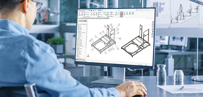
4. Following the drawings-model approach
The world is moving towards 3D for easy design communication. But heavy dependence on 2D drawings by fabricators and shop floor engineers make 2D drawings indispensable. So when models are created using drawings approach, drafters can easily generate final fabrication drawings. Platforms like AutoCAD® have provisions for this with inbuilt tools like section plane, live section, add jog, create block, Flatshot etc.
This conversion preserves design intelligence in models and the design intent is conveyed accurately to the shop floor. It will lead to fewer rejections and enable delivering drawings closer to the pre-defined quality parameters.
Get the right drawing approach for your project
Creating the specification list separately involves heavy drafting work. But with the drawings-model approach this can be avoided. In fact, the benefits for accuracy don’t end here; with model-drawings approach, there is much more.
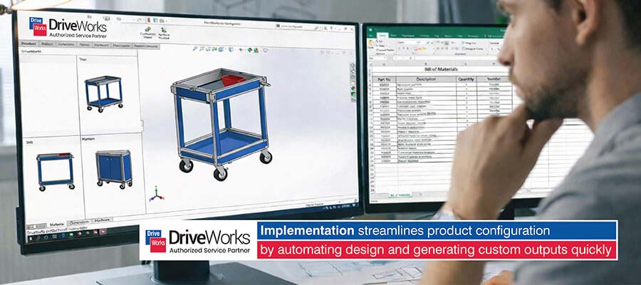
“What is the most important thing you produce from 3D models?” the audience asked Chris Naujok, a SolidWorks expert, during his presentation.
“Bill of materials!” he replied without a second’s delay.
Yes, BoMs needed during fabrication can be easily generated from model. Thus, to calculate the correct quantity takeoffs for parts to be purchased or manufactured, one needs to get the models accurate.
Conclusion
For today’s fast moving fabrication industry, achieving high levels of accuracy is of the utmost importance. Especially for metal fabricators who depend upon drawings created by an external CAD drafting expert team. Slight compromises in drawings could lead to erroneous fabrication, compromised quality of final product, and reduced operational life of the machine tools.
Following best practices can play a critical role in improving drawing accuracy by leaps and bounds. Not only that, accurate drawings result in fewer ECOs from shop floor, save tools from extensive wear and tear, and allow planning of fabrication to complete within stipulated timelines.
Our CAD drafters help you save time with drawing accuracy
Discuss your project →
Leave a Reply

is a mechanical design engineer at TrueCADD – a company invested in industrial CAD drafting, modeling, and design automation. Ms. Trivedi writes about solution finding approach in CAD and design automation challenges backed by her years of exploration in industrial designing in furniture, millwork, and metal fabrication designs.
Related Posts
Need help on an ongoing basis?
We establish long term business relationships with clients and are committed to total customer satisfaction.
Home |
Sitemap |
Privacy Policy | Data Security & Confidentiality |
Contact us |
![]()
For example, it is assumed that the X mm diameter of the hole can be punched using a tool of X mm. While in reality, the diameter is X+n mm, where n is the clearance between the tool and metal sheet for heat dissipation through air.