Assembly drawings define relationships between product parts by showing how each part fits and works together. These drawings help in analyzing tolerances, support the integration of engineering and manufacturing disciplines and make sure that all aspects of a product life cycle are communicated to everyone from design through production, installation and maintenance.
Leading CAD Outsourcing Company offers solutions of Engineering CAD Services, Design Drafting & 3D Modeling
Email us:
info@truecadd.com
info@truecadd.com
Leading CAD Outsourcing Company offers solutions of Engineering CAD Services, Design Drafting & 3D Modeling
Understanding Assembly Drawings: Purpose, Process, and Best Practices
Updated on June 2nd, 2026
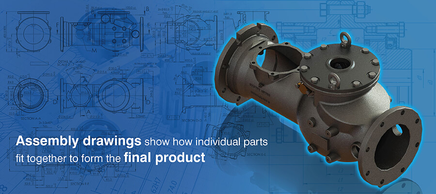
Table of Contents
- What are assembly drawings and their importance
- Types of assembly drawings and their applications
- How to create accurate assembly drawings
- Assembly drawing software: Tools and recommendations
- Best practices for creating good assembly drawings
- How assembly drawings enhance communication and project coordination
- Conclusion
Inadequate assembly drawings lead to confusion and conflict between workers as people may interpret the design differently according to their own experiences and opinions.
This confusion can be avoided with detailed assembly drawings which define how each part fits into the larger assembly. These technical drawings, besides reducing scope for misinterpretation and helping to optimize production, also make post production maintenance and troubleshooting easier.
What are assembly drawings and their importance
The purpose of assembly drawings is to demonstrate integration, i.e., how finished components combine and maintain their relationships among assembled components. They allow tolerance stack up analysis to make sure that the assembly functions properly regardless of whether parts have reached their maximum allowable manufacturing tolerances.
They help communicate the assembly sequence by displaying exploded views using route lines indicating physical interference or impossible assembly sequences.
Assembly drawings are fundamentally different from shop drawings that describe the fabrication of individual components and fabrication drawings that explain the fabrication processes used to construct individual components.
These crucial engineering design documentations are extremely important in all phases of a product’s lifecycle like manufacturing, field installation, service/maintenance operations and quality control.
Reduce rework with accurate, first-time-right mechanical assembly drawings.
Get a free quote »Types of assembly drawings and their applications

There are several types of assembly drawings included within engineering design documentation. Each type serves a unique function.
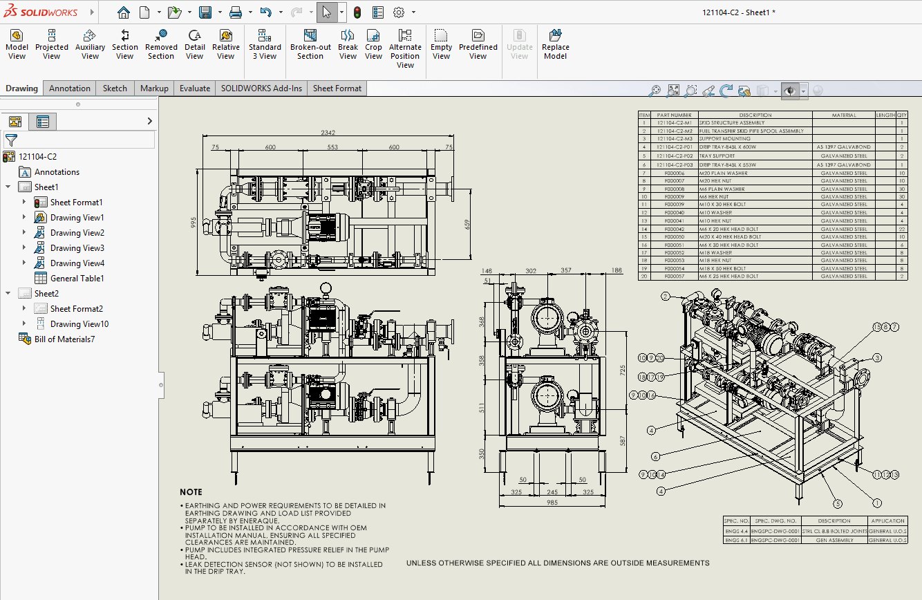
1. General assembly drawings
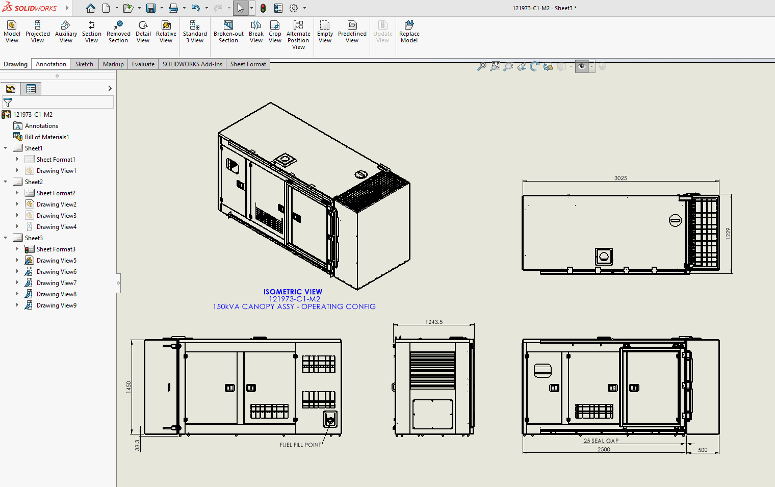
This is an overall view of the finished product and displays all parts of the finished unit in its final operating position. They include part numbers, important measurements and reference designators used for Bill of Material entry.
Use of general assembly drawings:
The production planner uses this type of drawing to determine the flow sequence of work and where the most bottlenecks occur in the assembly process. The quality inspector will also refer to this type of drawing to verify that all required parts are present and properly positioned during the final inspection.
2. Exploded assembly drawings
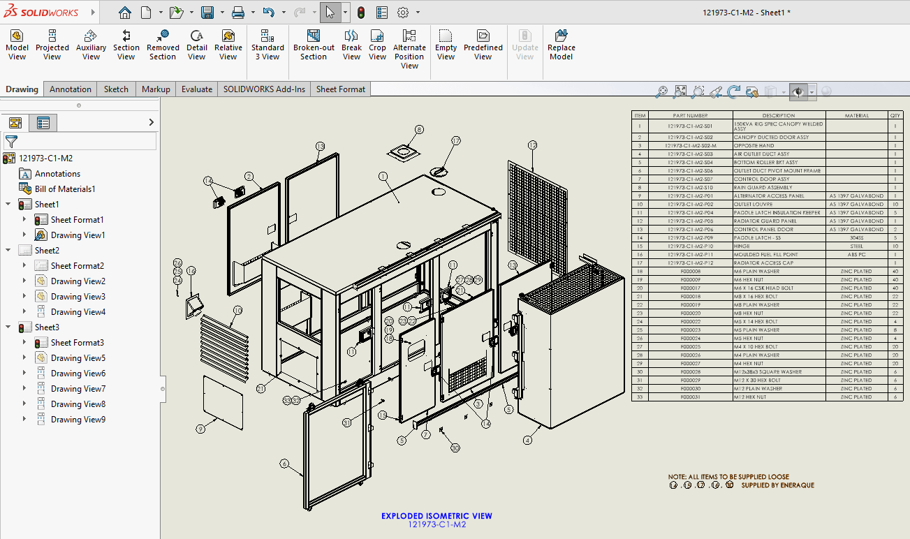
Exploded assembly drawings separate components from 1 another in a way that mirrors their most direct path of disassembly (i.e., removing parts in the order they were installed). By using an exploded format, the position of every part is preserved with respect to the parts it’ll connect to during assembly by referencing them to common datum planes, such as alignment axes or centerlines.
Use of exploded drawings:
Exploded views are used frequently in instructional materials for consumer products, to assist the end user who has no technical experience with assembling the product. Maintenance personnel often use exploded views to aid in troubleshooting and to visualize the arrangement of internal components within a device without having to disassemble the entire unit.
3. Detailed assembly drawings
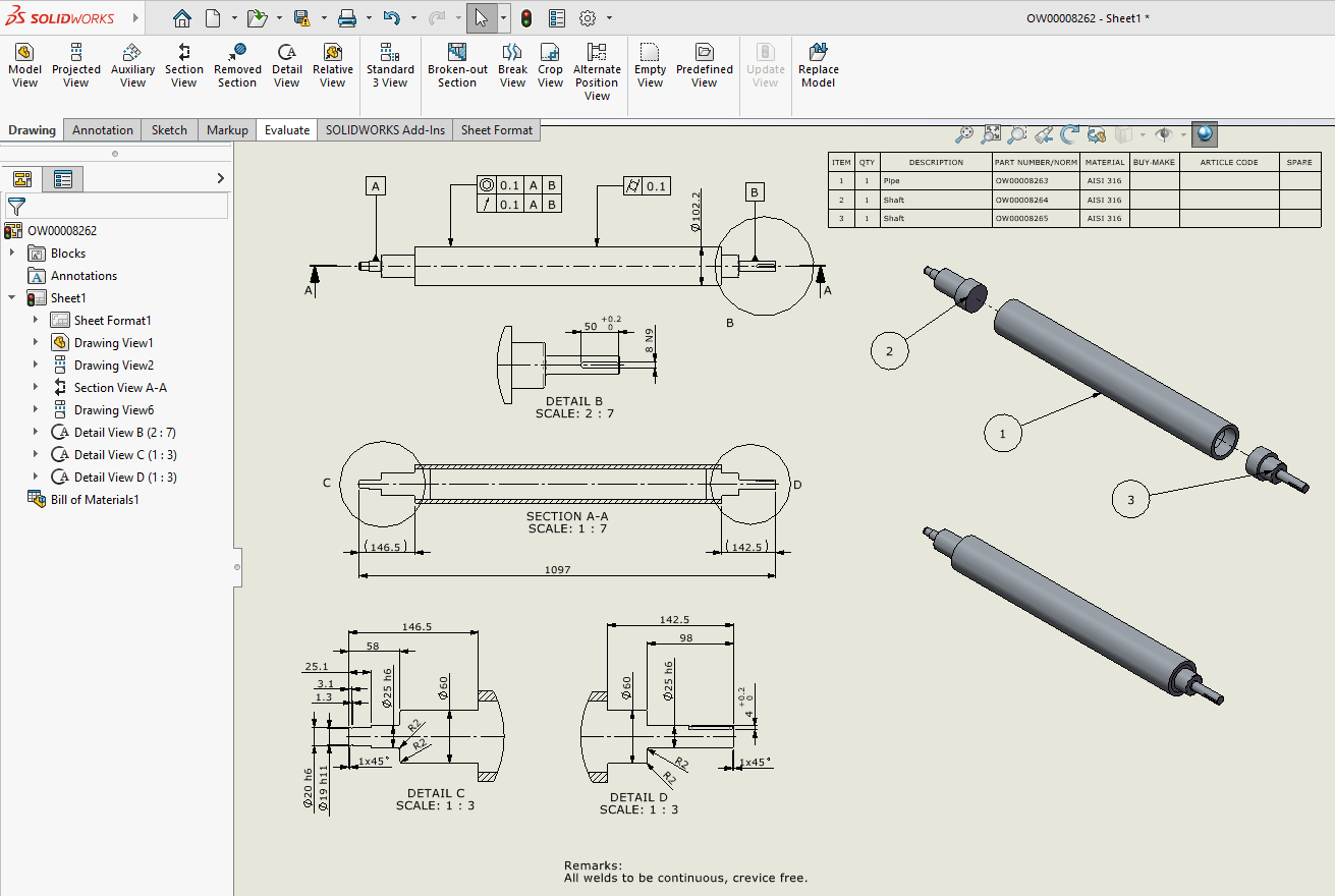
Detailed assembly drawings provide information about dimensions, geometrical tolerances and materials of a high precision assembly. The drawings have narrow tolerance bands for critical fit relationships and the surface finishes of mating surfaces as well as assembly torque values for fasteners.
Use of detailed assembly drawings:
These types of drawings are necessary when creating subassemblies that are highly precise i.e., dimensionally accurate. Examples include mechanical drawings of bearing housings, gear assemblies and valve mechanisms, which all require detailed assembly documentation to function correctly.
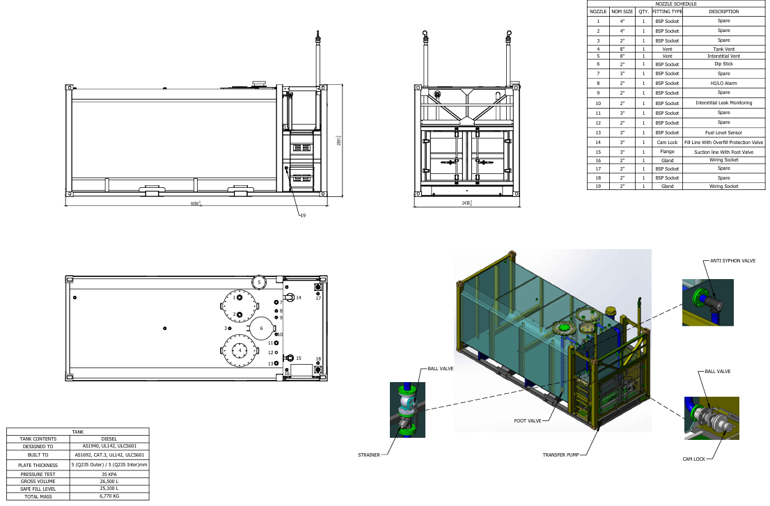
4. Outline assembly drawings
Outline assemblies depict an exterior view of an assembled product layout, without a detailed view of the internal components that make up the assembly. We use these drawings as a means to identify mounting dimensions, location points for connections and the physical space required by the product.
Use of outline assembly drawings:
Initial design concepts for products can be reviewed using outline assembly drawings as a conceptual level view of the product’s architecture without detailing specific design solutions.
5. Schematic assembly drawings
Assembly schematics are used to display the functional relationships among components rather than their physical shape or form.
Electrical schematics display electrical components (e.g., resistors, capacitors, integrated circuits) using symbols. Similarly, HVAC Schematics display duct work, dampers and air handling units as well as airflow arrows and indicate airflow path through the system.
Use of schematic assembly drawings:
An installation team or maintenance personnel using this type of drawings will be able to understand how all parts connect together without having to draw to scale.
6. Subassembly and fitted assembly drawings
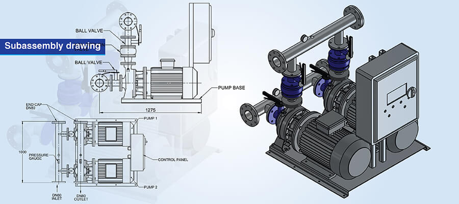
Subassembly drawings identify specific groups of parts (modules) that make up the total assembly. The drawings identify the subassembly as an independent item having its own part number and dimensions.
Fitted assembly drawings show the product in its final assembled configuration after all adjustments, shim and alignments have been made.
Use of subassembly and fitted assembly drawings:
Subassembly drawings are used for modular construction to allow for simultaneous manufacturing of multiple subassemblies by various groups.
For complex products such as those found in aerospace, marine, etc., subassembly and fitted assembly drawings are used to simplify the management of complex assembly processes through the use of hierarchical structure diagrams.
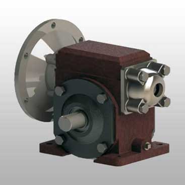
Conversion of PDF to 3D CAD for a Reducer Gear Assembly
A heavy engineering casting component manufacturer needed to convert PDF 2D drawings and sketches of a reducer gear assembly into accurate 3D CAD assembly drawings. Since the PDF drawings were non editable, the company couldn’t update their designs or align them to manufacturing capabilities.
TrueCADD took the PDF drawings of the reducer gear assembly and created accurate 3D CAD models with all relevant engineering data (i.e., assemblies and part relationships). A team of experts preserved the intelligent data from the original design throughout the conversion process and produced usable CAD models aligned to manufacturing specifications.
The final deliverables were:
- Editable 3D CAD models ready for design modifications
- Designs aligned to manufacturability
- Reduced errors and simplified production hand‐off
 Gear Assembly CAD Conversion
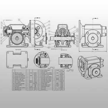 Converted 2D to 3D CAD Models
How to create accurate assembly drawings
From concept to final documentation, assembly drawings follow a structured method.
Step 1- Define the purpose
You need to be sure of the level and role of the user of the document and its purpose. You also need to clearly identify whether it’s an arrangement drawing, a standard assembly drawing or an inseparable assembly drawing.
Step 2- Gather and organize design data
Collect the drawings of each component, specifications of materials, fasteners used within the assembly and interfaces between components.
Step 3- Draw or import individual components
Use libraries to import 3D models of each component into the CAD software at current revision level.
Step 4- Assemble components in CAD software
Position components using mating constraints that accurately represent the actual assembly relationship and physical connection between the components.
Step 5- Create assembly views
Prepare exploded views with trace lines showing the exact path for insertion. To simplify the appearance of the drawing group fastener kits along a single trace line.
Step 6- Add annotations and balloons
Add identification balloons systematically with match drilling callouts, transfer punching instructions and torque values with tightening sequences.
Step 7- Include dimensions and tolerances
Add the overall dimensions of the assembly, critical interface dimensions and the tolerances which affects the ability to assemble the unit.
Step 8- Prepare Bill of Materials (BOM)
Develop a hierarchical listing of components used within the assembly, including part numbers, description, quantity and specifications.
Step 9- Review and revise
Review with manufacturing engineers, quality personnel and assembly technicians and include their comments prior to production.
Ensure manufacturing accuracy with tolerance-driven assembly drawings.
Contact Us »Assembly drawing software: Tools and recommendations
The following table compares some majorly used software for product assembly drawing:
 AutoCAD
- 2D/3D Modeling: 2D drafting with limited 3D; reference-based assembly
- Exploded Views: Manual static creation; requires flatshot
- BOM Automation: Non-associative tables; AutoCAD Mechanical adds limited 2D associativity
- Version Control: Autodesk Vault/Docs; often uses standard file servers
- Primary Strength: Universal 2D layout standard; legacy data compatibility; extensive symbol libraries

- SolidWorks
- 2D/3D Modeling: Parametric history-based; intuitive mate-based assembly
- Exploded Views: Configuration-stored within assembly files; motion study animations
- BOM Automation: Associative configurable tables; automatic updates; weldment cut list strength
- Version Control: SolidWorks PDM Standard/Professional; Windows Explorer integration
- Primary Strength: Fastest learning curve; mid-market standard; large user community

 PTC Creo
- 2D/3D Modeling: Parametric history-based; strict constraint solver
- Exploded Views: View manager saved states; Creo Illustrate for advanced animations
- BOM Automation: Programmable repeat regions with complex filtering capabilities
- Version Control: Windchill PLM; web-based enterprise lifecycle management
- Primary Strength: Handles massive assemblies; unmatched surface modeling; enterprise-grade stability

- Autodesk Inventor
- 2D/3D Modeling: Parametric history-based; joint/constraint assembly approach
- Exploded Views: Dedicated presentation files (.ipn) for explosions and snapshots
- BOM Automation: BOM Manager with independent structure editing
- Version Control: Autodesk Vault with deep integration; efficient copy design workflows
- Primary Strength: Any CAD technology for non-native file handling; tight AutoCAD DWG integration; iLogic rule-based automation

All these platforms help you with dimensional constraints, updates when designs change and collaboration through integrated version control. For organizations looking for 3D CAD drawings for product development to take this next level with these tools are effective investments.
Best practices for creating good assembly drawings
Following established practices in creating an effective assembly drawing lets you clearly convey the instructions and minimize potential errors in the design process:
Consistent part identification and sequencing of balloons: Balloons are used to link to Bill of Material (BOM) entries with the least amount of ambiguity. All numbers associated with the balloons should be sequential and follow the order of assembly.
Separate parts using exploded views: Parts are positioned far apart to allow a user to see all aspects of the assembly but close enough to allow for visual association of individual components.
Sectioning with material specific hatching: Sectioning for assembly is usually done following ASME Y14.2 guidelines. Each type of material is used according to its own pattern. When adjacent parts are sectioned, the hatch angle of the 2 sections should be in opposite directions.
Put in assembly level GD&T and tolerance notes: The functional interfaces should be controlled using profile tolerancing referenced to master datum structures. Critical gaps that must remain within specified limits should be identified as reference dimensions and labeled as such if those gaps are controlled by cumulative part tolerances.
Integrate structured BOMs with phantom assembly logic: The automated generation of assembly drawings minimizes the possibility of transcription errors that can occur when manually preparing the documents. Subassemblies should be represented using phantom assemblies and discrete components promoted to the top level BOM for correct purchasing.
Follow established standards consistently: Conventions for dimensioning, tolerance and symbology are governed by ISO 128 and ASME Y14.5, which provides a common language understood worldwide. Follow them thoroughly in the drawings.
Manage revisions and eliminating circular references: : Revision blocks are used to document all changes including who authorized the change. Top down designs should use skeleton references to prevent PDM data corruption.
Review prior to releasing: Manufacturing engineers will review for feasibility issues, Quality teams will review for inspection accessibility and purchasing will confirm the clarity of sourcing information.
How assembly drawings enhance communication and project coordination
Mechanical drawings for assembly documentation are 1 source of the truth that provides every stakeholder a common understanding of the assembly.
You reduce errors and rework with clear assembly instructions. With Model Based Definition (MBD) and semantic Product Manufacturing Information (PMI), coordinate measuring machines (CMMs) can be programmed for inspection routines without having to rely on humans, which also reduces the number of engineering change orders.
Skeleton models allow multiple designers to work on interfacing components concurrently using the master reference geometry. If the skeleton model’s references change then any dependent assemblies will also update, thus allowing multiple designers to work in parallel. Say for example chassis skeleton reference changes will be reflected in engine mount designs and frame designs, so there won’t be version conflicts between the two.
Field changes to as built documents provide maintenance teams with access to vendor part numbers, installation specs and torque requirements, reducing downtime. Technical data packages connect STEP Files, inspection plans and approved vendor lists to provide the correct materials and processes.
Conclusion
Assembly drawings are a time tested and production tested way of documenting an engineer’s intentions for manufacturing. They’re also used to provide instruction on installation and operation/maintenance of a product and are used to reduce error both in production and later during the product’s use.
CAD helps you create and edit assembly drawings more efficiently and with greater precision than using legacy 2D drafting workflows. And CAD based workflows also provide greater collaboration between designers and engineers. This improves overall manufacturing process efficiency by increasing clarity about the work among all parties.
So learning assembly drawing techniques and knowing about the best type of assembly drawing for your specific needs will allow you to produce documents at a professional level and help up your production processes
Ensure perfect fit and function with high-quality assembly documentation.
Get drawings now »
Harika Singh
Harika Singh is a published author with over 20 years of experience working with leading organizations in India and the United States. She develops authoritative content on BIM, CAD, VDC, digital engineering, and construction technology. Her expertise lies in translating complex technical concepts into actionable insights that help AEC professionals improve collaboration, efficiency, and project outcomes.
Related Posts


Need help on an ongoing basis?
We establish long term business relationships with clients and are committed to total customer satisfaction.
Home |
Sitemap |
Privacy Policy | Data Security & Confidentiality |
Contact us |
![]()