CAD tools that support Design for Manufacturing (DFM) strategies are a major game-changer when it comes to getting the most out of sheet metal doors and windows design. By optimizing production workflows, these tools make your products look better and stronger. By cutting down on engineering lead times, keeping production costs low these tools help you stay ahead of the competition.
Leading CAD Outsourcing Company offers solutions of Engineering CAD Services, Design Drafting & 3D Modeling
Email us:
info@truecadd.com
info@truecadd.com
Leading CAD Outsourcing Company offers solutions of Engineering CAD Services, Design Drafting & 3D Modeling
Enhancing the Efficiency in Sheet Metal Doors and Windows Design
Updated on May 21st, 2026
The market for metal doors will have a projected compound annual growth rate of 5.7% from 2022 to 2032. If manufacturers of architectural metal doors and windows want to cash in on this growth, they need to get their design-to-fabrication process sorted. And that means having the right tools for the job. Advanced sheet metal design tools with built-in automation capabilities are what’s going to help you stay ahead of the competition.
The United States accounts for a majority of North America’s sheet metal market revenue, around 60.0% to be exact. To stay ahead in this field, manufacturers need better techniques for sheet metal fabrication for doors and windows. That means getting to grips with advanced CAD tools and DFM strategies, so that products look great but also meet high standards of accuracy and manufacturability.
By focusing on these areas, teams can knock days off their engineering lead times. They can achieve same-day delivery with no compromise on quality.
Table of Contents
Why focus on sheet metal door and window design?
Getting a grip on how sheet metal works and the basics of Design for Manufacturability (DFM) is really crucial if you want to create fully custom metal doors or if your objective is metal door and window design optimization.
Knowing what’s a reasonable minimum bend radius for your metal (which can vary depending on the grade) will save you when it comes to issues like parts not fitting together right or your doors and windows not working quite as smoothly as they should.
And when you are working with advanced fabrication techniques, like roll forming and using grooves and ribs in the right places, you can really boost the strength and functionality if you do the right metal door and window detailing.
Key design considerations in designing sheet metal doors/windows
The trickiest things about designing accurate doors and windows are the issues that occur during sheet metal engineering design. Professional metal door frame design services have a deep understanding and experience of the physics and the manufacturing process. Because in the real world, metal components don’t behave quite the same way they do on the computer screen.
The following parameters for sheet metal door design and window design are what you need to keep your design looking like what you intended, while also keeping an eye on the bottom line and making sure your doors and windows get manufactured efficiently.
Minimum bend radius for metal door frames
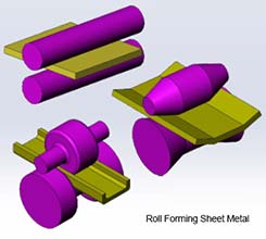 Fig. 1
Bending radius is a make or break factor and it’s not the same for every type of sheet metal. When it comes to metal door and window frames and plinths, the bending process is key in sheet metal fabrication for doors and windows.
But if you get the radius wrong, you can end up with rabbet flatness issues when doors are installed. That can cause all sorts of problems with installation and operation.
There’s a basic rule of thumb that says for mild steel sheet metal the minimum bending radius should just be the thickness of the sheet. But that’s not the only thing that comes into play.
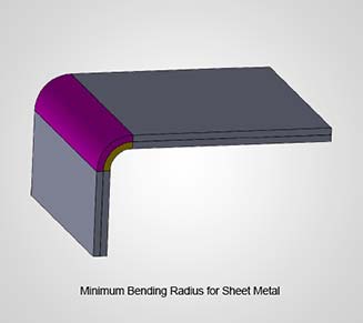 Fig. 2
The type of brake tool you’re using also matters. Roll-forming is pretty common for bending in door and window frames. (See fig.1) Now when you’re trying to bend a sheet to a specific angle, you’ve got to watch out for springback. That is just the sheet metal’s natural tendency to go back to its original flat form.
It happens because the top surface of the sheet is getting stretched while the underside is getting squished. So it acts like putting pressure on a piece of paper and then letting it go.
To counter this, brake operators have to over bend the sheet so it ends up where they want it when the pressure is released.
Remember: Designers need to plan for spring back in door and window designs. This can help you avoid change orders during manufacturing. And this improves your sheet metal fabrication workflow efficiency
Find out how optimal is your bending radius.
Talk to an expert »Hole, rib, and groove design for sheet metal windows
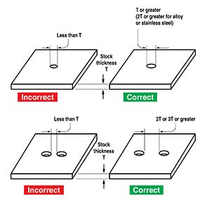 Fig. 3
While holes let you fasten metal doors and windows with hinges, they also make formed parts stronger. The metal around a punched or drilled hole stretches and gets more flexible, which gives the whole a bit more structural strength in your metal panel design. But you need to think carefully about the size of the hole and how far apart they are before you start punching or drilling in (see Fig. 3).
One rule of thumb is that the hole shouldn’t be smaller than the thickness of the metal sheet, and the distance between holes needs to be at least twice the thickness of the sheet. For stainless steel or alloy materials, the hole gets bigger, up to twice the thickness of the sheet.
Making sure you maintain the ratio between the size of the hole and the thickness of the sheet is really important. If you punch holes that are too small to go through the material then the stamping force ends up spreading out sideways instead of going straight down through the material (see Fig. 4).
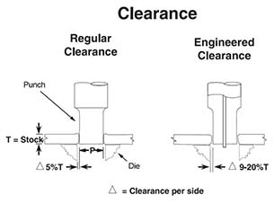 Fig. 4
When the ratio gets disturbed, punches get stuck in the metal and parts can end up being bent or deformed altogether. All of this means the cost per run goes up and you have to spend longer and more money on maintenance, which holds up the whole fabrication process.
Grooves and ribs add a bit more strength without having to make the wall thicker, and they’re used a lot in doors and windows to help create a tight seal when the sections come together. And they can actually make the punching process a bit easier.
Remember: Include all these elements in your design right from the start, so you can avoid problems when you’re punching in the holes.
Get the right DFM strategy for your sheet metal doors.
Request a proposal »Notch and tab standards in sheet metal door design
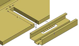 Fig. 5
Sheet metal doors and windows design requires that doors and windows have notches and tabs for hinges and locks. Several parameters to keep in mind when making notches. (See Fig 5)
To design notches according to the standard guidelines, the rule of thumb is to make sure the notch is at least 1.5 times as wide as the sheet is thick and that the length is no more than five times that thickness.
Remember: Remember When placing notches, it is essential to leave enough room at the bend so that is at least three times the material thickness plus the inside bend radius. If you have two notches, the distance between them needs to be at least double the thickness of the sheet.
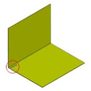 Fig. 6 Wrong method
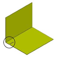 Fig. 7 Right method
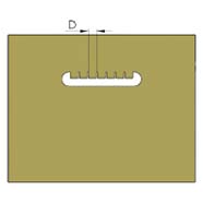 Fig. 8
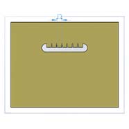 Fig. 9
Minimum flange width guidelines in metal doors
Flanges on doors and windows are horizontal channels that help stiffen the top and bottom of the door. The reveal flange for example is a key part of the door frame that sticks out from the wall. When you’re working with flanges make sure the minimum height of the bend is in proportion to the thickness of the material, how tight the bend is and how long the bend is.
Remember: You need to give yourself at least enough room to fit in some bend relief – the minimum width for that should be equal to the material thickness or 1.50 mm – whichever is bigger.
Welding alternatives
Welding does a great job of joining two bits of metal together, but the question is can you avoid welding altogether and get away with using just fasteners? The answer is yes, and it can greatly reduce the cost of your sheet metal door assembly workflow.
For instance, if you use knockdown metal door jambs instead of welding them in place, you can save a bunch on your welding bill. However, these jambs aren’t always best for interior finishes like drywall or plaster.
One simple way to eliminate welds is to attach the brackets to the base material instead of making them a separate part. This makes a big difference on the bottom line.
Remember: Before you decide to ditch the welds and go back to the drawing board, you need to take a hard look at what kind of bending technology you have available in the shop.
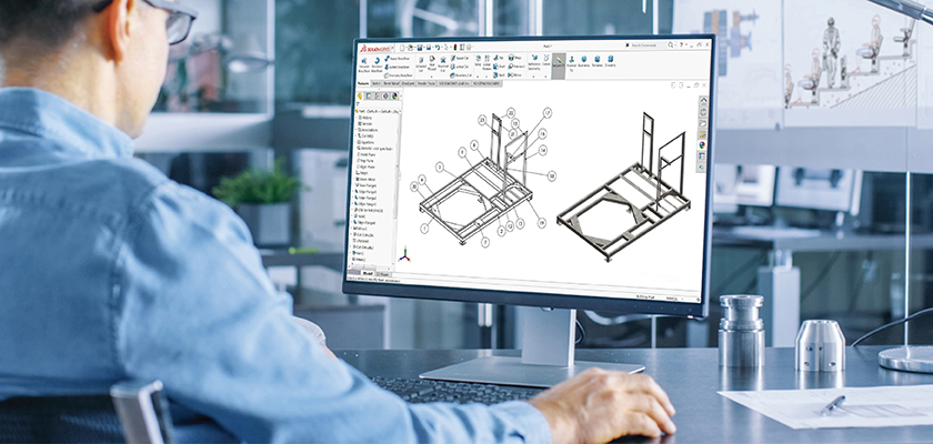
CAD tools for sheet metal doors and windows design
While you must remember these design principles, to achieve better results you also need the right tech tools that support that DFM strategy and make the sheet metal fabrication workflow easier. These tools give designers a ton of flexibility to design a sheet metal part in very less time and generate door and window fabrication drawings that the professionals on the shop floor need to get to work.
Popular 3D parametric tools like SolidWorks and Autodesk Inventor have all the features you need to get sheet metal parts right. You can get all the forming and welding details in place using 3D modelling for metal doors and windows. Plus, they’ll automatically generate flat patterns with bend compensation, so you can get a head start on your production timelines.
Whether it’s a sheet metal door, window, or even a complicated assembly, SolidWorks has got you covered with all the tools you need for high quality results. And when it comes to modelling sheet metal frames, SolidWorks’ custom metal door frame drawing CAD capabilities simplify it with its dedicated modules for generating highly optimized designs.
Don’t have the right CAD tool for design? Relax, we have got you covered.
Contact Us »Integrating design automation in sheet metal door and window design
Once 3D sheet metal design tools have become a part of your workflow, you find that you can start automating the repetitive design tasks through automated sheet metal design processes. The benefits of design automation really start to shine through when you’re working on a custom metal door or window that’s specifically designed to meet a building’s unique needs.
From being able to automatically generate 3D models and flat patterns, all the way to cut lists and fabrication drawings, this kind of automation can cut down your design cycle times and really make a big difference to your sheet metal manufacturing efficiency.
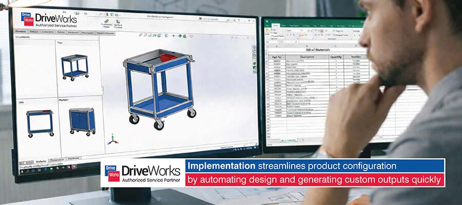
Tools like DriveWorks for SolidWorks and iLogic for Inventor take this to the next level by giving you the tools you need to develop sales configurators for doors and windows. These configurators make it easy for customers to input their sizes and configuration requirements, and instantly get a 3D model and an estimated price to go with it.
This kind of CAD/CAM for sheet metal integration really streamlines the whole design to manufacturing process.
Metal door manufacturer speeds up design cycle by 70% using design automation
A US-based hollow metal doors and frames manufacturer was really struggling with design data getting all over the place. Custom orders weren’t clearly defined and their engineers were wasting a lot of time on repetitive tasks, which was causing all sorts of delays and mistakes.
TrueCADD implemented a DriveWorks-based configurator that automatically generated 3D CAD models and manufacturing drawings from a set of input parameters. The sales teams could just input the customer’s specifications and get the design documents back in no time.
This resulted in:
- 70% cut in design cycle time
- Over 70,000 doors and frames designed
- Much better quality and faster response in getting orders fulfilled
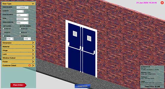 Online Configurator for Metal Door
 3D Door Components Customization
FAQs on sheet metal door and window design
-
Converting static 2D sections into intelligent 3D assets allows you to build a library of standard jambs and headers. This means you can reuse components for new custom window and door assemblies in a fraction of the time it takes to draft.
-
Nesting software arranges flattened door skins and frame profiles on the sheet to maximize material usage. This reduces raw metal cost per window unit and simplifies the laser cutting process for complex layouts.
-
Parametric models link the Bill of Materials (BOM) to the design geometry. If a door size changes the BOM updates automatically for hinges, locks and glazing beads, eliminating procurement errors and installation delays.
-
Yes. Rules-based automation configures variable dimensions and hardware logic instantly. This means you can generate fabrication drawings for bespoke hollow metal doors and complex window elevations without manual drafting or calculation errors.
-
Specialized services provide scalable resources to handle the overflow during high-demand construction periods. They deliver code-compliant shop drawings and flat patterns fast so your internal engineers can focus on product innovation not routine drafting tasks.
Final Word
As demand for custom sheet metal doors and windows keeps on growing, manufacturers are going to have to start using more advanced design techniques if they want to stay ahead of the game. By bringing together the right sheet metal doors and windows design principles, CAD tools and design automation know-how, they can create accurate and high quality products, get orders out the door way faster, and cut costs to boot.
By adopting these innovations production processes get a speed boost and profitability increases, giving manufacturers a real edge in the market.
Touch new heights for your door-window design.
Get a free quote now »
Usha B. Trivedi
Usha B. Trivedi is a mechanical design engineer at TrueCADD – a company invested in industrial CAD drafting, modeling, and design automation. Ms. Trivedi writes about solution finding approach in CAD and design automation challenges backed by her years of exploration in industrial designing in furniture, millwork, and metal fabrication designs.
Related Posts
Need help on an ongoing basis?
We establish long term business relationships with clients and are committed to total customer satisfaction.
Home |
Sitemap |
Privacy Policy | Data Security & Confidentiality |
Contact us |
![]()