Sheet metal designs are bound to fail at the shop floor if the CAD models carry \unclear bend data, wrong thickness values or mismatches among CNC coordinates. You can avoid these issues and send your design intent intact to the cutting table with 8 SolidWorks techniques ranging from module selection and K-factor setup to forming tools and flat pattern validation.
Leading CAD Outsourcing Company offers solutions of Engineering CAD Services, Design Drafting & 3D Modeling
Email us:
info@truecadd.com
info@truecadd.com
Leading CAD Outsourcing Company offers solutions of Engineering CAD Services, Design Drafting & 3D Modeling
SolidWorks Sheet Metal Modeling: 8 Expert Techniques for Fabrication-Ready Designs
Updated on June 2nd, 2026
Table of Contents
- Why engineers choose Solidworks over other CAD tools for sheet metal: A practical comparison
- 8 Solidworks sheet metal modeling techniques that improve fabrication outcomes
- 5 common Solidworks sheet metal modeling mistakes (and how to avoid them)
- Solidworks sheet metal in practice: project examples from TrueCADD
- Solidworks 2024–2025 sheet metal updates worth knowing
- FAQ’s on SolidWorks Sheet Metal Modeling
- Summary: Solidworks sheet metal best practices at a glance
- Need expert Solidworks sheet metal design support?
In sheet metal fabrication, it’s not easy to make sure that your design intent survives the trip from brief to shop floor. And any lack of design clarity will lead to scrap and rework, and of course, deadline misses. Most of these issues stem from a lack of clarity about the design intent when the actual work, like bending, welding, or punching, is done. 3D CAD-based sheet metal modeling helps to bridge these gaps with reliable outputs that fabricators can actually work with.
Our team at TrueCADD has delivered over 200 large sheet metal projects, and we know the challenges in sheet metal workflows and how to design error-free flat patterns and fabrication-ready parts. Whether you are a design engineer or CAD modeler, the 8 sheet metal design techniques we share in this article will help you reduce errors in work and have better output.
Why engineers choose Solidworks over other CAD tools for sheet metal: A practical comparison
Due to both its standards and features, big OEMs, outsourcing companies and fabrication shops all prefer using SolidWorks for sheet metal design. Its dedicated sheet metal environment is a godsend for calculating bends automatically, managing gauge tables and generating flat patterns. And it does not need the manual workarounds many other tools need. Because its parametric modeling engine makes sure all design changes propagate automatically across drawings, parts and assemblies. This helps to reduce errors and avoid mid-project revisions.
With SolidWorks you can stop the parameter inconsistencies and errors that come from switching tools, and can do all sheet metal design tasks within a single environment. The tool guides you through all sheet metal design essential steps, from material selection to flat pattern validation, bend parameters and others.
SolidWorks sheet metal approach comparison
| Approach | Best For | Flat Pattern Accuracy | Complexity |
|---|---|---|---|
| Base Flange/Tab Method | Standard bent parts | High | Low |
| Insert Bends | Thin-wall conversions | Medium | Medium |
| Convert to Sheet Metal | Imported geometry, complex shapes | Medium-High | High |
| Lofted Bend | Hoppers, transitions, HVAC ducts | High | High |
8 Solidworks sheet metal modeling techniques that improve fabrication outcomes
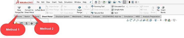
1. Always start in the sheet metal module (not the standard part environment)
You can save yourself from mistakes like designing any feature, which won’t generate flat patterns downstream by first assigning the component as a sheet metal part in SolidWorks. To do this in the right way, select Insert > Sheet Metal > Base Flange/Tab and launch the module. This makes SolidWorks load properties specific to sheet metal, including material thickness, bend radius defaults, and relief types, making it easier for the designer to work with thin plates and sheets.
If you begin working in the standard SolidWorks environment and not in the sheet metal module, then you will have to face flat pattern errors and rework later when you try to convert. The sheet metal module ensures your design carries accurate bend information from the very first sketch, whether you add edge flanges, miter flanges, hems or tabs or any other feature.
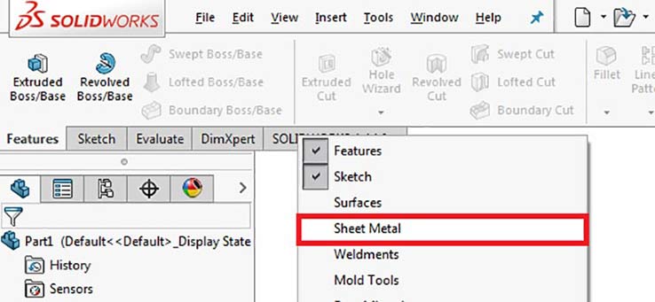 Sheet Metal Module in SolidWorks
When to use the weldments module alongside sheet metal
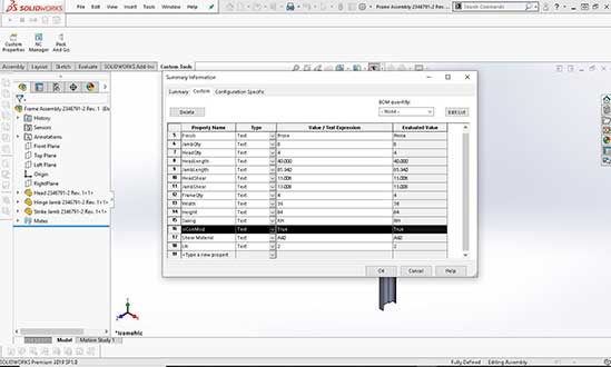
The Weldment module offers preloaded profiles so you can automatically generate machined part and welding part configurations from your 2D and 3D sketches. So it’s convenient to use the module in parallel with the sheet metal module if your assembly includes welded structural members such as frames, supports, or enclosures. Also, the design table helps you to store and reuse hundreds of configurations of things like structural channels and tubes from your CAD library.
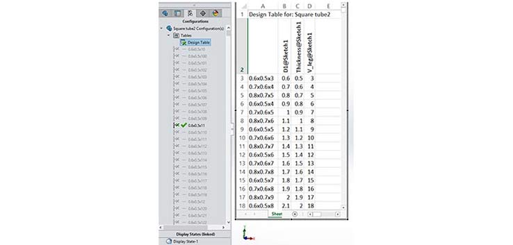 Configurable Custom Weldment Profiles in SolidWorks
2. When to convert a solid body to sheet metal — And how to do it without errors
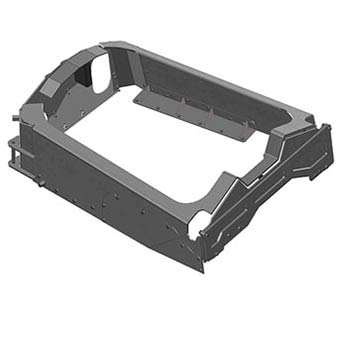
It is not a fixed practice to always start a feature or part directly in the sheet metal module. Items like hoppers for SPMs, HVAC ductwork, or transition pieces, that have complex geometries, are usually modeled first as solid bodies or surfaces, and then converted. For this, you use the Insert > Sheet Metal > Convert to Sheet Metal workflow.
 Sheet Metal Options in SolidWorks
Especially for non-standard shapes, you can reduce time and complexity when you adopt this approach, as this cuts down the total modeling steps you’d otherwise need to take. So, for example, when designing a hopper it is easier to first model it in the standard environment in SolidWorks and then convert the solid part to the required thickness using the shell function. It would take many steps to do the same if you had designed the hopper in the sheet metal module from start. Keep in mind, however, that conversion to sheet metal will work smoothly only if you make sure that no internal fillets clash with the bend radius, and all faces of the part have the same thickness.
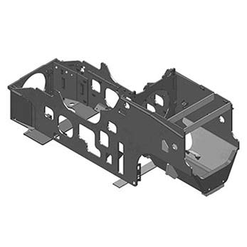 Complex Sheet Metal Designs
 Sheet Metal Designs
3. How to set K factor and bend allowance in Solidworks for accurate flat patterns
The cutting accuracy of CNC press brakes and laser cutters is controlled by the accuracy with which the flat patterns reflect the part’s unfolded size. And this flat pattern accuracy is determined in turn by the K-factor set by the designer. In SolidWorks sheet metal environment, the K-factor is represented by a simple formula K = t / T, with t being the neutral axis and T being the thickness of the material. So the K factor fixes the ratio of the distance from the inside face of a bend to its neutral axis, divided by material thickness.
 Sheet Metal Understanding K Factor
Typical K factor values by material
| Material | Typical K Factor |
|---|---|
| Mild Steel | 0.44 |
| Aluminum | 0.33 |
| Stainless Steel | 0.50 |
| Copper / Bronze | 0.35 |
Once you set the K factor, SolidWorks will take that input and auto calculate flat patterns for each bend. You start this in the Sheet Metal Parameters panel and go to the Bend Allowances. Here you will find a dropdown menu where you select K-factor and then enter the value. If your fabrication shop has preset values, you can provide them instead to put into the Bend Allowances or Bend Deduction fields.
 Sheet Metal Parameters
Bend Allowance vs. Bend Deduction: Both of these values are used and needed for accurately building flat patterns. However, preferring one over the other depends on the press brake calibration data of individual fabrication shops. While Bend Allowance gives the arc length of the neutral axis between bend lines, Bend Deduction gives the difference between the actual length of the flat pattern and the total of outside dimensions.
4. Use gauge tables instead of manual thickness entry
Entering thickness values for each part by hand is a recipe for errors and inconsistencies because individual designers can use different values. To avoid such errors, we use Gauge Tables in SolidWorks and standardize part values and validate against uniform data. This ensures the material thickness, bend allowance/deduction and bend radius for the part is uniform across design and fabrication.
In most workshops, the fabrication teams build custom gauge tables in Excel to match the shop capacities and standards, though SolidWorks does come with a default set of gauge tables for common materials. The shared custom gauge table provides the source of truth for all designers and fabricators and prevent inconsistencies in thickness and flat pattern errors. It is stored in a shareable location with access for those working on the job. You set up the gauge table under the Sheet Metal feature by selection the ‘Use gauge table’ option.
 Hopper Model
5. Build large assemblies using top-down parametric modeling
For large sheet metal assemblies, it is good to first create a master layout sketch and define all key reference planes and assembly dimensions. This helps you to fully use SolidWorks’ top-down modeling and save time. Team members can refer to and link the master layout when designing any individual part. And this ensures all related parts are updated whenever there is any change in even a single parameter in any part across the project. This makes large sheet metal assemblies work smoothly as you do not have to worry whether changing a single parameter, say the overall enclosure width, would lead to mismatches and misses.
 Sheet Metal Exercise in SolidWorks
With the top-down approach accommodating multiple client design revision requests cease to be a problem. As you don’t need manual updates for the dozen of parts and drawings for each change, response becomes faster on all fronts. Hardware insertion, like placing fasteners into holes, also speeds up with drag-and-drop and auto-snap freeing you from the need to keep clicking in sequence over and over.
6. How symmetry and CNC coordinate alignment reduces material waste
Set the model origin in SolidWorks to match the CNC cutter or press brake’s home position before you begin modeling. For correct fabrication, the coordinates of your CAD model must match that of the target CNC machine. For this, you need to set your model origin in SolidWorks against the CNC cutter or press brake’s home position, and only then start work. This will ensure your digital sheet metal models are good enough to support direct manufacturing.
By using symmetry from the beginning of the design process you can greatly reduce modeling time and material waste. Use mirror features and symmetric mates in assemblies to make sure the parts are evenly balanced. With symmetry as your key approach, you can optimize nesting better during fabrication because you can rotate and pack symmetric flat patterns on the raw sheet stock more efficiently. Center-based symmetry also provides more manufacturing flexibility downstream and prevents rework.
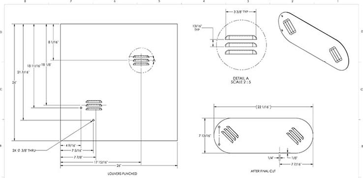
7. Leverage forming tools for louvers, lances, and embossed features
Very common sheet metal deformations and parts like louvers, lances, dimples and embossing features are carried out using the forming tools in SolidWorks. You simply drag a tool from the Design Library onto a sheet metal face and apply the deformation. However, there are two things to know about this workflow. You need to use the Position tab to place the tool at the correct insertion point and press the Tab before releasing the drag.
The first step ensures the tool does not float undefined but is placed at punch location properly, and the second step helps to flip or rotate the tool to punch from the correct side or direction.
The tool automatically adjusts to the material thickness and updates the flat pattern. But keep in mind that actually the tool deformation geometry is set by the punch model itself. What adjust to that geometry are the flat pattern representation and how the inside radius behaves in relation to the thickness. If your inside bend radius on the forming tool is smaller than what it should be given the material thickness, the tool will fail or end up with invalid geometry.
For custom forming tools, model the die geometry and define the stopping face using the Forming Tool command on the Sheet Metal tab, then save as .sldftp file. Without a defined stopping face, the depth of the deformation is undefined and the tool is unusable, and defining Faces to remove clarifies about the openings. If you are using legacy .sldprt files, then at the beginning of work you also need to right-click and designate the Design Library folder as a Forming Tools Folder, otherwise the drag and drop will fail to work. This allows your team to reuse proprietary punch geometries by ensuring the flat pattern accurately reflects the manufactured part, with all formed features.
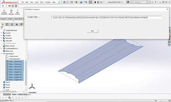
8. Validate flat patterns before sending to fabrication
Before you think of exporting flat patterns for laser cutting or CNC punching, you need to validate them in SolidWorks using the Flatten feature. Be sure to check that all bends unfold without issues, none of the faces overlap, and your bend calculations match overall dimensions. Once these checks are done, you can safely export the flat pattern as a DXF file. For this, select the “Flat pattern geometry” option and click File > Save As > DXF.
You need to set up routine verification checks to run before exporting the DXF file. This increases accuracy and much reduces rework and scrap. Common flat pattern validation checks used for these checks include verifying the positioning of bend lines and ensuring that the relief cuts are proper for the given material thickness. You also need to be sure that the flat pattern boundary and the expected unfolded dimensions match each other.
5 common Solidworks sheet metal modeling mistakes (and how to avoid them)
- Using boss-extrude instead of base flange: Boss-Extrude is used to create a solid feature that does not carry sheet metal properties. In this case the flat pattern will fail or produce incorrect results if you do not use the Base Flange/Tab to start the sheet metal parts.
- Setting incorrect bend radius for the material gauge: Every combination of material and thickness conforms to a minimum bend radius. Using a radius which is smaller than that allowed by the material causes cracking at the bend. To prevent such cracking, always use your material supplier’s specifications or gauge tables for values.
- Not enabling “Normal Cut” for angled tab-and-slot joints: If the Normal Cut is not enabled, then the tabs on angled faces will cut perpendicular to the sheet and not normal to the face. The gaps you find during assembly come mostly from these errors. You can prevent such issues by enabling the Normal Cut in the Tab and Slot feature dialog.
- Skipping gauge tables and entering manual thickness: Inconsistencies will appear across a multi-part assemblies when thickness values are entered by hand. If one part uses 1.5 mm and another uses 1.52 mm, the rounding off will compromise the assembly fit. You have to use gauge tables to enforce uniform values in such cases.
- Ignoring CNC coordinate alignment before modeling: A rookie error is to miss setting the CAD model origin to match the CNC machine’s home position. In such a case, the nesting software cannot optimize material usage. You need to set the origin at the start of modeling to avoid having to manually reposition flat patterns before you can begin cutting.
Solidworks sheet metal in practice: project examples from TrueCADD
Case Study 1: Doors and Frames Manufacturer — Design Automation
Industry: Steel doors and frames manufacturing
A leading doors and frames manufacturer was beleaguered by design cycle times stretching to over 15 days for each product variation. Producing the variants required manual adjustment of the models in SolidWorks, and this drag was delaying schedules, besides adding errors.
Design tables linked to Excel spreadsheets, parametric sheet metal models with configurable dimensions, and automated BOM generation.
Design system optimization and automation helped reduce the timeline from 15 days to a few hours per variant. Using the design table helped to churn out hundreds of product configurations from a single master model without needing to adjust by hand.
 Door and frame Design Customization
 CAD Library Integration
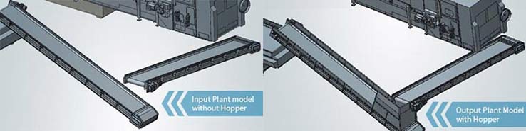
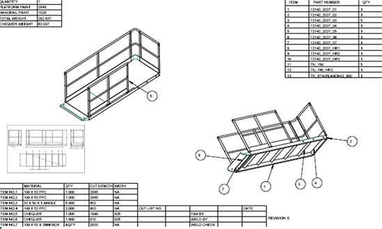
Case Study 2: Recycling Plant Equipment — Parametric Hopper Design
Industry: Recycling plant equipment manufacturing (Ireland)
There were enormous delays and too many errors faced in designing sheet metal hoppers. Each hopper was being modeled individually, and there was no system to auto update design changes across the assembly.
Top-down parametric assembly modeling with master layout sketches, lofted bends for hopper transitions, and design tables for size variants.
Was able to design 55 hoppers per month with parametric models which updated automatically whenever client changed specifications. The client could expand manufacturing operations by relying on the partnership.
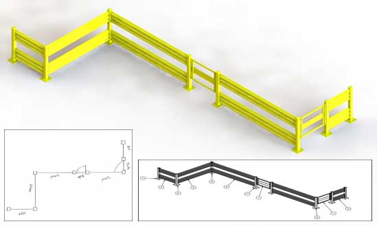 Gaurdrail 2D Drawings and 3D Model
 Handrail CAD Drawings
Solidworks 2024–2025 sheet metal updates worth knowing
Keeping your SolidWorks skills current by staying on top of the latest release features helps improve productivity. Here are most relevant sheet metal updates from recent versions you should know about:
- 2024 Tab and Slot Propagation: The number of features needed for a complex assembly has greatly reduced. Now Tab and Slot features can be propagated across multiple edges in a single operation.
- 2024 Rip Tool for Cylinders and Cones (2024): You can now directly convert rolled sheet metal bodies into flat patterns with no need to split the edges manually. You can do this because the Rip tool now supports both cylindrical and conical faces.
- 2025 Bend Notches for Manufacturability (2025): You can automatically add relief notches at bend intersections by using the new bend notch options. This brings down the risk of the material forming cracks at tight-radius bends, thus improving manufacturability.
If you work with complex transitions and rolled geometries, and your fabrication shop does not use these updates, you need to take a hard look. If you are still using SolidWorks 2023 or earlier, upgrading can change your efficiency. Just the Tab and Slot propagation improvement can save you much time during multi-edge assemblies.
FAQ’s on SolidWorks Sheet Metal Modeling
-
Bend allowance is the arc length of the neutral axis between the bend lines. Bend deduction is the difference between the sum of the outside flange dimensions and the flat pattern length. Both of these methods can produce accurate flat patterns with values from your press brake calibration data.
-
There are two simple ways. Either open the sheet metal part and click the “Flatten” button in the Sheet Metal toolbar, or right-click the Flat-Pattern feature in the FeatureManager and select “Unsuppress.” SolidWorks will generate the flat pattern based on your K factor, bend allowance, or bend deduction settings. Then export the pattern as a DXF for use in the fabrication shop.
-
Yes. For this, you need first to save the flat pattern as a DXF or DWG file using File > Save As, and select “Flat pattern geometry.” You need to verify the flat pattern includes bend lines and forming tool markers for the fabrication to run without issues.
-
SolidWorks already comes with default gauge tables for common materials. These are in the installation directory (typically under Lang > English > Sheet Metal Gauge Tables). The gauge table gives you starting points for your design. So, you will start with the “sample – steel gauge.xls” table when working with mild steel and then customize it according to the actual material, thickness and bend radius.
-
You use the forming tools in SolidWorks to simulate punch deformations such as louvers, lances, and dimples. For this, you usually drag a forming tool from the Design Library onto a sheet metal face. SolidWorks adjusts the feature to the material thickness and reflects the forming tool location on the flat pattern.
-
For this, use Insert > Sheet Metal > Convert to Sheet Metal. You first select a fixed face and then identify its bend edges and rip edges. SolidWorks will convert the solid body into a sheet metal part with bend features and will output a flat pattern. Before conversion, you need to make sure that all faces have uniform thickness.
-
Using DFMA means keeping fabrication and assembly priorities in mind from the beginning of sheet metal modeling and designing. This obviously focuses on cutting down the number of bends and the part count by leveraging SolidWorks features. It also means you have to ensure the bend requirements match available tooling and flat patterns validate against the CNC machine’s capabilities.
Summary: Solidworks sheet metal best practices at a glance
To maintain the accuracy of flat patterns from the first feature, ensure starting in the Sheet Metal module
- Where it is impractical to do direct sheet metal modeling because of complex geometry, begin with solid bodies and convert to sheet metal later.
- Use the formula K = t / T to set the correct K factor and bend allowance for your material.
- To enforce consistency, avoid manual entry of thickness and other values and use default and custom gauge tables.
- Use top-down parametric modeling when designing for large assemblies. With this, you can automate propagation of all design changes across the assembly.
- Focusing on symmetry will reduce material waste. And ensure that the model origins are aligned with CNC coordinate systems.
- Use the forming tools for louvers, lances, and embossed features and avoid manual cut-and-extrude operations.
- Never neglect to validate flat patterns and catch and fix errors before exporting DXF files.
Need expert Solidworks sheet metal design support?
TrueCADD provides SolidWorks sheet metal design and drafting services for fabrication shops, OEMs, and manufacturers. Our team of certified SolidWorks engineers is expert in all sheet metal design tasks, from parametric modeling and design automation to flat pattern validation. You will get production drawings and output ready to put directly into your CNC workflow.
Contact Us →
Harika Singh
Harika Singh is a published author with over 20 years of experience working with leading organizations in India and the United States. She develops authoritative content on BIM, CAD, VDC, digital engineering, and construction technology. Her expertise lies in translating complex technical concepts into actionable insights that help AEC professionals improve collaboration, efficiency, and project outcomes.
Related Posts
Need help on an ongoing basis?
We establish long term business relationships with clients and are committed to total customer satisfaction.
Home |
Sitemap |
Privacy Policy | Data Security & Confidentiality |
Contact us |
![]()