Different types of MEP drawings offer detailed plans for mechanical, plumbing, and electrical systems, ensuring seamless integration in construction projects.
Leading CAD Outsourcing Company offers solutions of Engineering CAD Services, Design Drafting & 3D Modeling
Email us:
info@truecadd.com
info@truecadd.com
Leading CAD Outsourcing Company offers solutions of Engineering CAD Services, Design Drafting & 3D Modeling
What are the Different Types of MEP Drawings?
Updated on June 2nd, 2026

The Fundamentals of MEP Drawings
MEP drawings are necessary for illustrating the layout and specifications of MEP components within a building. Whether these are mechanical drawings, electrical drawings, or plumbing drawings, together, they ensure accurate coordination and installation of critical building systems. These include heating, cooling, water supply, power and drainage. Coordinated and clash-free MEP drawings facilitate communication between key construction stakeholders, including architects, engineers, and contractors, for a smooth construction process.
Knowing the different types of MEP drawings helps a wide AEC audience understand their significance on a practical level. By understanding nuances of each MEP drawing type and their significance for architects, engineers, and contractors, we can understand their specific uses.

9 Types of MEP Drawings Used in Construction Projects
1. Mechanical / HVAC Drawings
Mechanical / HVAC drawings illustrate the structure and function of various mechanical systems to support engineers and manufacturers for the accurate creation of MEP components and equipment.
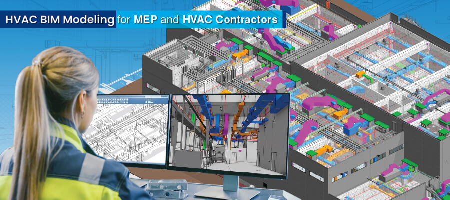
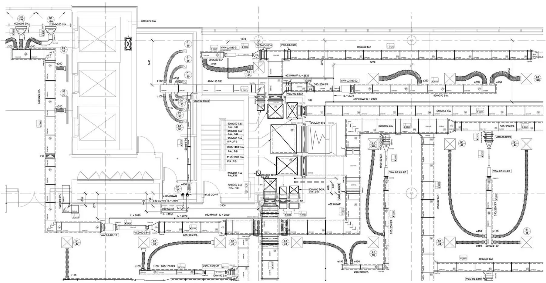 HVAC Systems Drawings
- Components and Systems: These drawings provide detailed intricacies of HVAC systems to help understand the various components that contribute to efficient heating, ventilation, and air conditioning. For example, using HVAC drawings for the optimal selection of energy-efficient HVAC components leads to reduced operational costs in commercial buildings.
- Air Distribution Layouts: These layouts show the layout of air distribution systems, which is crucial for maintaining optimal air quality and temperature within a structure. For example, using HVAC drawings to design precise air distribution in hospital HVAC systems enhances environmental control in critical areas.
- Ductwork and Piping Schematics: These drawings help stakeholders examine the detailed schematics of ductwork and piping that are essential for the efficient flow of air and fluids throughout the building.
2. Plumbing Drawings
Plumbing drawings outline pipe configuration, fixtures, and other plumbing equipment for buildings. These plumbing layouts are critical for plumbing professionals to install, repair, and alter plumbing equipment efficiently.
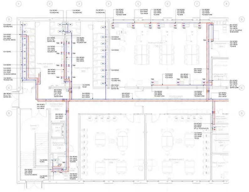 Plumbing Drawings
- Water Supply and Distribution: These drawings are blueprints of water supply systems that help in identifying key elements, such as piping layouts and fixture locations, and the placement of valves for optimal control. These drawings are often used in designing sustainable water supply systems for residential complexes that incorporate water-recycling technologies. As an MEP BIM services provider, we ensure that these systems are precisely modeled for efficiency and accuracy.
- Drainage and Sewage Systems: These drawings provide a detailed network of drainage and sewage systems to ensure proper disposal and treatment of wastewater. These include detailed sizing and slopes of pipes crucial for maintaining proper drainage. Sanitary and storm drain systems are designed for the safe disposal of sanitary and storm water. For example, they are often used in designing stormwater management systems for commercial developments to reduce flood risks.
- Fixture and Appliance Locations: These drawings help stakeholders understand the strategic placement of fixtures and appliances, thereby optimizing functionality and user convenience. These drawings are often used for the strategic placement of fixtures in hotels to enhance guest satisfaction and operational efficiency.
- Gas Distribution: These drawings display the layout of gas distribution systems, ensuring a safe and efficient supply of gas. They also help identify safety measures to be implemented to reduce risks associated with gas distribution. They are popularly used for purposes such as implementing gas leak detection systems in commercial kitchens to prevent potential hazards.
3. Electrical Drawings
Electrical drawings depict the layout of electrical equipment within devices or buildings to showcase circuits, connections and components. They serve as a roadmap for electricians during onsite installation and maintenance runs.
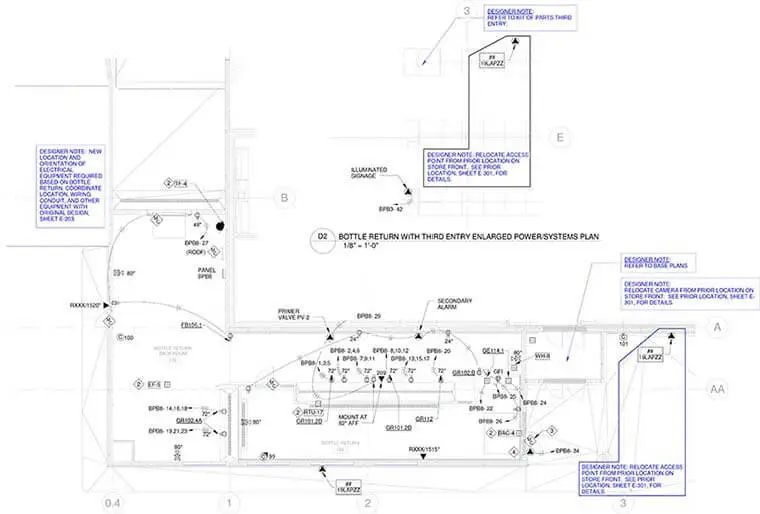 Electrical System Drawing
-
Power Distribution
- Electrical Panels and Subpanels: These drawings show the distribution of power through panels and subpanels to help stakeholders get a better understanding of the electrical backbone of the building. Wiring diagrams map out the electrical connections, ensuring a safe and reliable power supply to various areas and sections of a room or a building.
- Load Calculations: These drawings help understand the calculations involved in determining the electrical load, which is a critical aspect for designing robust power systems.
-
Lighting Systems
- Circuiting and Control Lighting Layouts: These drawings provide intricate detailing regarding the circuiting and control systems that govern the lighting within a building. They also show the specific placement of lighting fixtures, considering both the aesthetic and functional aspects of illumination.
- Emergency Lighting: These drawings help stakeholders examine emergency lighting systems designed to ensure occupant safety during unforeseen events.
4. Fire Protection Drawings
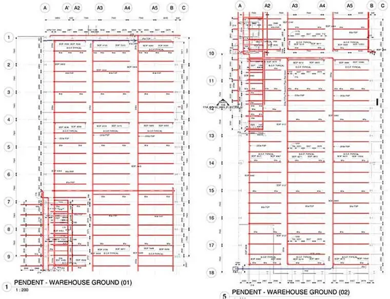
Fire protection drawings are used to outline fire safety features, including sprinklers, alarms, and emergency exits in a building. They serve as crucial deliverables for architects, engineers, and firefighters to ensure occupant safety during emergencies.
 Fire Protection Drawings
- Fire Alarm and Life Safety
- Detection and Notification Devices: These drawings help stakeholders understand the deployment of devices that detect and notify occupants in case of fire or other emergencies. Installing advanced detection devices at specific locations in places such as warehouses prevents false alarms and ensures quick response.
- Alarm Zones and Sequencing: These drawings provide detailed zoning and sequencing of fire alarm systems, which are critical for effective emergency response. Designing fire alarm systems for high-rise buildings optimizes alarm zones for efficient evacuation.
- Sprinkler Systems: They help to understand the design and layout of sprinkler systems, crucial for fire prevention and control.
- Fire Suppression Systems: They provide a detailed understanding of the intricacies of fire suppression systems, designed to contain and extinguish fires.
5. Coordination Drawings
Coordination drawings play a vital role in integrating multiple building systems to ensure that conflicts don’t occur in physical space. They not only provide risk reduction in construction projects but also enable seamless collaboration between various trades and improve construction efficiency.
- Clash Detection and Resolution: The process of detecting and resolving clashes between different MEP systems during the pre-construction stage ensures seamless integration.
- Spatial Coordination of MEP Systems: MEP coordination improves the building design and the coordination of systems within the spatial constraints of the building optimizes efficiency.
- Composite Drawings: The creation of composite drawings brings together multiple disciplines, providing a holistic view of the building’s MEP systems.
6. Penetration Drawings
Penetration drawings showcase openings within building elements to guide contractors in the installation of cables, pipes, and ducts without negotiating structural strength and quality. These drawings ensure utilities are integrated accurately and completely within the proposed building design.
These drawings are also called Block-out and sleeve drawings outline openings within concrete structures to allow the movement of MEP components. These drawings are critical for accurate coring or cutting during field installation and for ensuring smooth integration of MEP services.
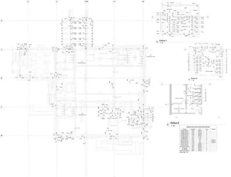 Penetration Drawings
7. MEP Shop Drawings
MEP shop drawings for building contractors deliver in-depth layouts for mechanical, electrical and plumbing systems to support them for fabrication and installation of MEP systems precisely within the set layout. These MEP shop drawings are essential for coordinating and constructing efficiently.
8. Pipe Spool Drawings
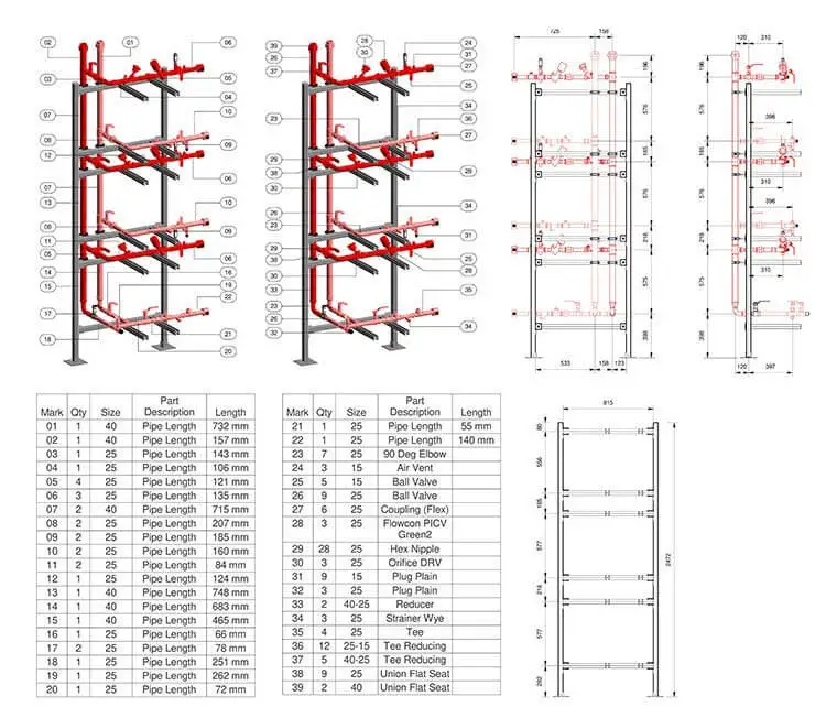 Pipe Spool Drawings
Pipe spool drawings showcase prefabricated sections of piping systems to aid manufacturers with accurate fabrication. These drawings are detailed to improve efficiency within construction projects and reduce installation costs and time.
9. As-built Drawings
As-Built drawings record the final state of an infrastructure or building to incorporate changes performed during construction. They serve as a strong authority to renovate, maintain or expand buildings in the future.
Advancements in automation and AI for MEP drawing creation
Advancements in AI and automation have transformed the creation of MEP drawings in construction sector. AI-based algorithms enriched with machine learning (ML) capabilities can assess complex architectural designs and create accurate MEP layouts accurately and seamlessly. This technology enables auto detection, clashes and ambiguities, reduction in human errors, and significant time savings in the design phase.
Furthermore, automation technology and tools optimize the placement of MEP equipment for optimized efficiency and cost effectiveness. Architects and engineers can focus on creative project aspects, while AI-driven systems reduce repetitive tasks, causing streamlined workflows, greater innovation and greater building sustainability.
Conclusion
Mechanical, electrical, and plumbing drawings, including MEP shop drawings, are the backbone of modern-day construction and serve as critical drawings for key systems. Detailed schematics deliver essential information on connection specifications and layouts to ensure seamless integration of MEP elements. Accurate MEP drawings in the construction industry, including shop drawings, are pivotal deliverables that guarantee safety, functionality, and productivity.
In a world of connected construction, coordinated and clash-free design requires professionals to stay updated with evolving design practices. Embracing new tools and workflows ensures improvements in project results, supported by better efficiency and smooth communication. Perpetual skill development not only boosts expertise but also contributes toward innovation, sustainability, and successful projects to motivate MEP professionals in the field.
Get customized MEPF Revit models and shop drawings.
Enhance MEP fabrication and installation efficiency

Harika Singh
Harika Singh is a published author with over 20 years of experience working with leading organizations in India and the United States. She develops authoritative content on BIM, CAD, VDC, digital engineering, and construction technology. Her expertise lies in translating complex technical concepts into actionable insights that help AEC professionals improve collaboration, efficiency, and project outcomes.
Related Posts


Need help on an ongoing basis?
We establish long term business relationships with clients and are committed to total customer satisfaction.
Home |
Sitemap |
Privacy Policy | Data Security & Confidentiality |
Contact us |
![]()