A practical guide to HVAC BIM modeling for MEP and HVAC contractors, covering HVAC systems, equipment, and how a Revit and Navisworks workflow delivers clash-free coordination, fabrication-ready shop drawings, and a smoother install.

Leading CAD Outsourcing Company offers solutions of Engineering CAD Services, Design Drafting & 3D Modeling
Email us:
info@truecadd.com
info@truecadd.com
Leading CAD Outsourcing Company offers solutions of Engineering CAD Services, Design Drafting & 3D Modeling
HVAC BIM Modeling: A Practical Guide to HVAC Systems, Coordination & Design for MEP Teams
Updated on June 12th, 2026
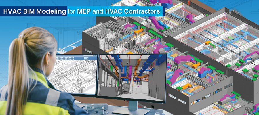
Table of Contents
- HVAC fundamentals: What the system does?
- HVAC equipment and how each type is modeled in BIM
- How BIM improves HVAC design and coordination
- Clash-free HVAC model for a Hospital Project in Ireland
- HVAC BIM deliverables and levels of development (LOD)
- Energy efficiency ratings and how they enter the model
- Future trends in HVAC and BIM
- Frequently asked questions
- Conclusion
Anyone who runs HVAC scopes for a living already knows the real truth. The thing that decides whether a job makes money or bleeds it is rarely the equipment. It is how well the system gets modeled, coordinated, and detailed before anyone lifts a duct into place. That is the whole point of HVAC BIM modeling. It puts heating, ventilation, and air conditioning into one 3D model, where clashes get sorted out on screen, fabrication is drawn to real sizes, and equipment is checked against everything else in the building.
This guide walks through HVAC systems and equipment from a BIM modeling point of view, then shows how a Revit and Navisworks HVAC BIM workflow keeps coordination clash-free, drawings fabrication-ready, and the install on track. It draws on real project work behind MEP 3D modeling services and HVAC design services for contractors and consultants in the US, UK, and Europe.
HVAC fundamentals: What the system does?
An HVAC system has four basic jobs. Each one affects how the ducts, pipes, and equipment are laid out, sized, and coordinated in the Revit model, so it is worth being clear on them before modeling starts.
| Function | What it does | Why it matters in BIM |
|---|---|---|
| Temperature | Heats and cools to hold a setpoint, using furnaces, boilers, coils, and refrigerant, controlled by thermostats. | Decides which equipment you pick and how much plant-room space it needs. |
| Air quality | Filters and cleans the air to remove dust, allergens, and pollutants. | Affects filter banks, air handler sizing, and the clearance you leave for maintenance. |
| Humidity | Adds or removes moisture to keep the air comfortable and safe. | Drives equipment choice (such as ERV vs HRV) and where condensate has to run. |
| Air movement | Pushes conditioned air around the building through fans and ductwork. | The duct network is the single biggest thing you coordinate against structure and other trades. |
HVAC shows up everywhere, from comfort in homes and offices to process protection in industry, infection control in hospitals, and basic wellbeing in schools, hotels, and transport. The tighter the ceiling and plant spaces, the harder the coordination, and the more a model pays for itself.
HVAC equipment and how each type is modeled in BIM
No need to list every product out there. Here is a working overview of the main equipment families you will actually deal with, plus a note on how each one shows up and gets coordinated in your HVAC BIM model.
Heating: Furnaces and Boilers
Gas, electric, and oil furnaces, plus steam and hot-water boilers, differ in fuel, how fast they respond, whether they add humidity, and how much upkeep they need. In the model, heating plant is built from Revit families that carry the data that matters, such as capacity, connections, and the clearance for service. What really gets coordinated here is the plant-room layout, the flue and vent routes, and the pipe runs out to the terminals.
Ventilation
Ventilation swaps stale indoor air for fresh outdoor air. That keeps oxygen up, clears out pollutants, and helps control humidity. Two recovery units come up a lot:
| Feature | Energy Recovery Ventilator (ERV) | Heat Recovery Ventilator (HRV) |
|---|---|---|
| What it moves | Recovers both heat and moisture from the air on its way out. | Recovers heat only, not moisture. |
| Best for | Humid climates. Saves energy and helps indoor air quality. | Cold climates. Focused on saving heat. |
| Trade-off | Costs more and needs extra upkeep because it handles moisture. | Simpler, cheaper, and lower maintenance. |
Fans come in two main types. Axial fans (think propeller and tube-axial) move a lot of air at low pressure. Centrifugal fans push against the higher pressure you get in ducted systems. Picking and sizing the right fan for each duct run is part of the design, and it gets checked in the model against the airflow needed. One point worth getting right in a spec is that centrifugal and axial fans are two different families, not the same thing.
In the BIM model, ductwork, ERVs, HRVs, fans, and grilles are built as Revit MEP families routed through the ceiling space, and the duct network is the part that gets coordinated hardest against structure and the other trades.
Air Conditioning
Common setups include split, window, ductless mini-split, central, packaged, and VRF/VRV systems. In the BIM model, the indoor and outdoor units, the refrigerant and condensate run, and the duct and diffuser layout are modeled as Revit MEP families, with the routing checked for clashes against everything sharing the ceiling and riser space.
System Types: Centralized, Decentralized, and Hybrid
- Centralized: A central plant conditions air or water and sends it out through ducts or pipes. You get consistent control and easier maintenance, but it costs more up front and is harder to change later.
- Decentralized (ductless): Mini-splits and window or wall units give you zoned control and an easy install in smaller spaces. They run out of capacity in large areas.
- Hybrid: Pairs something like a heat pump (for milder temperatures) with a furnace (for deep cold) to get better efficiency across the year.
Whichever type a project uses, the plant, distribution, and terminals are modeled the same way in Revit, and the BIM model is where the routing and clearances get coordinated before anything is built.
Get a quote for HVAC BIM modeling »
How BIM improves HVAC design and coordination
This is the part that actually pays off on an HVAC job. Going from 2D drawings to a coordinated Revit model changes when you catch problems, and how much they cost you. Here is where it shows:
1. Coordinating trades and finding clashes
HVAC almost never fails on its own. It fails where ductwork meets steel, sprinkler mains, cable trays, and plumbing in a ceiling that was tight to start with. Pull every trade into one model, run the clash checks in Navisworks, and you sort those conflicts out on screen, before anything gets built or hung. Every clash you fix in the model is a change order, an RFI, or a pile of site rework that never happens.
2. Getting the sizing and layout right
You can check duct runs, where the plant sits, and the space left for service against the airflow and access you need, all inside the model. That cuts down on the undersized or oversized kit that wastes energy and leaves rooms uncomfortable.
3. Shop drawings ready for fabrication
At a higher LOD, the model holds enough detail to fabricate from. So, your shop and duct drawings come straight off the coordinated model instead of being redrawn from scratch. That is cleaner work and a higher first-time-right rate.
4. A smoother install with fewer surprises
With coordinated drawings, accurate prefab, and a clash-free model, the install crew works from information that already lines up with every other trade. Less schedule risk, less rework.
5. A model you can actually use after handover
The equipment data, specs, and as-built geometry sitting in the model carry over into commissioning, O&M, and facility management. So, the effort you put in keeps paying off long after construction wraps up.
Clash-free HVAC model for a Hospital Project in Ireland
An engineering contracting company brought TrueCADD a hospital project in Ireland. It was exactly the kind of scope where HVAC coordination makes or breaks the program, with mechanical, plumbing, and fire-protection services all fighting for the same tight ceiling and plant-room space. The input was thin. There were 2D base drawings and markup sketches, and no 3D model to start from.
The TrueCADD team built the coordinated, clash-free HVAC, plumbing, and fire-protection models in Revit, then ran the whole thing through Navisworks to identify and resolve every clash before fabrication. From that one coordinated model came the shop drawings the contractor needed to fabricate and install. The clashes that usually turn into change orders and RFIs on site got caught and fixed on screen instead.
How the project was approached
- Trades modeled: HVAC (ductwork, equipment, diffusers), plumbing, and fire protection, all coordinated against structure and architecture in one model.
- Tools: Revit for the HVAC BIM modeling, and Navisworks for clash detection and coordination. That is the standard setup for this kind of MEP work.
- Level of Development: LOD 350 for coordination, LOD 400 for fabrication-ready detail. Set this to the actual delivered LOD.
- Inputs and outputs: 2D base drawings and markups went in. A coordinated BIM model, Navisworks clash reports, and shop and fabrication drawings came out.
What it delivered
- A 98% first-time-right (FTR) rate on deliverables. The model was right the first time, nearly every time.
- Real cost savings, because clashes got fixed in the model instead of on site.
- Shop drawings delivered in 4 weeks, keeping the install on track.
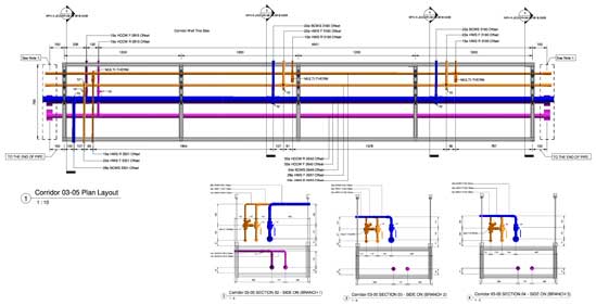 Corridor plan layout for plant room
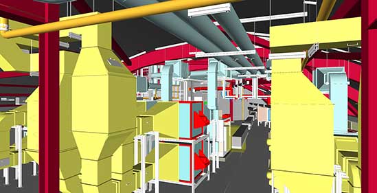 3D MEP coordinated model for plant room
HVAC BIM deliverables and levels of development (LOD)
“BIM” means different things at different stages. Setting the Level of Development (LOD) up front tells everyone what the model will actually contain, and what you can use it for.
| LOD | What the HVAC model gives you | Typical use |
|---|---|---|
| LOD 200 | Generic systems with rough size, shape, and location | Early design and space planning |
| LOD 300 | Specific systems, sized and placed accurately | Design development and documentation |
| LOD 350 | Built to connect with other trades for coordination | Clash detection across trades |
| LOD 400 | Detail and data good enough to fabricate from | Shop drawings and prefabrication |
| LOD 500 | Checked against what was actually built | Handover, O&M, facility management |
Typical HVAC BIM deliverables include the coordinated model, clash reports, duct and pipe shop drawings, equipment schedules, spool drawings, and as-built models. (These LOD levels follow common industry practice. Line them up with your project BEP and the standards you work to, such as ISO 19650.)
Energy efficiency ratings and how they enter the model
Efficiency targets and equipment ratings go into the MEP BIM model as data, and they feed the load and energy checks and the equipment selection. A quick reference:
| Rating | What it measures | Applies to |
|---|---|---|
| SEER2 / SEER | How efficiently a unit cools over a season. | AC units and heat pumps (cooling). |
| HSPF2 / HSPF | How efficiently a heat pump heats over a season. | Heat pumps (heating). |
| AFUE | How much fuel a unit turns into usable heat. | Furnaces and boilers. |
In the US, the DOE replaced SEER and HSPF with SEER2 and HSPF2 in January 2023. The newer ratings use a tougher test, so the numbers read lower than the old ones for the same equipment. On the renewable side, solar-assisted HVAC and geothermal heat pumps cut running cost and carbon, and their plant and routing are coordinated in the model like anything else.
Carrying these ratings as parameters on the equipment families in the BIM model keeps energy performance, equipment selection, and coordination working from one single source.
Future trends in HVAC and BIM
- Smart HVAC with AI and IoT: Controls that adjust themselves, live monitoring, and predictive maintenance that tunes energy use to who is actually in the building.
- Better energy management: Data and machine learning to cut energy use and downtime, increasingly linked back to the model and a digital twin.
- Indoor air quality: Better filtration and cleaning with live monitoring, which has become a bigger design priority since the pandemic.
- From BIM to digital twin: The coordinated HVAC model increasingly feeds a live twin that the facility team uses to run the building.
Frequently asked questions
-
It is building a coordinated 3D model of a building’s heating, ventilation, and air conditioning systems, including ductwork, equipment, piping, and terminals, with the data attached. You use it to find clashes, check sizing, produce shop drawings, and plan the install.
-
It catches clashes and routing conflicts in the model before construction, so you get less rework, fewer change orders, and fewer RFIs on site. Detailing that is ready to fabricate from also lifts your first-time-right rate and supports prefab.
-
The modeling is done in Revit, and clash detection and coordination run in Navisworks. Shop and fabrication drawings come straight out of that coordinated Revit model, so there is one source of truth from design through fabrication.
-
Fabrication and prefab usually need LOD 400, where the model has enough detail and data to build from. Clash detection and coordination are normally done at LOD 350.
-
Outsourcing to a specialist MEP BIM team brings in trained Revit and Navisworks people and extra capacity without the cost of hiring and tooling up. That helps a lot when workload swings or a job is on a tight program.
Conclusion
Knowing HVAC systems tells a team what the job has to do. A solid Revit and Navisworks workflow is what makes sure it can actually be built, clash-free, ready to fabricate, and on schedule. For MEP engineers, HVAC and specialty contractors, and building engineering consultants, that combination is what turns a set of MEP drawings into an install that goes to plan. Bringing in an extra set of hands for the modeling and coordination is one way to get there faster.
Talk to the TrueCADD HVAC BIM team about a project »










Harika Singh
Harika Singh is a published author with over 20 years of experience working with leading organizations in India and the United States. She develops authoritative content on BIM, CAD, VDC, digital engineering, and construction technology. Her expertise lies in translating complex technical concepts into actionable insights that help AEC professionals improve collaboration, efficiency, and project outcomes.
Related Posts
Need help on an ongoing basis?
We establish long term business relationships with clients and are committed to total customer satisfaction.
Home |
Sitemap |
Privacy Policy | Data Security & Confidentiality |
Contact us |