To achieve precision in sheet metal drawings you need to get the dimensioning absolutely right, specify every bend detail, make sure the flat patterns add up and also include clear material details. When your drawings account for the real-world fabrication challenges, you have high-quality fabrication, while avoiding costly delays, misread dimensions and tolerance issues.
Leading CAD Outsourcing Company offers solutions of Engineering CAD Services, Design Drafting & 3D Modeling
Email us:
info@truecadd.com
info@truecadd.com
Leading CAD Outsourcing Company offers solutions of Engineering CAD Services, Design Drafting & 3D Modeling
Top 6 Tips for Accurate and Efficient Sheet Metal Drawings
Updated on June 2nd, 2026
Table of Contents
- Key precision factors that shape clear sheet metal drawings
- Top 6 tips for precise and clean sheet metal drawings
- Tip 1: Structure sheet metal drawings for maximum readability
- Tip 2: Apply dimensioning techniques that improve accuracy
- Tip 3: Specify bend information clearly for error free forming
- Tip 4: Prepare flat patterns that ensure cutting and forming accuracy
- Tip 5: Communicate material and hardware details with clarity
- Tip 6: Use CAD tools effectively to improve drawing consistency
- How to maintain sheet metal drawing precision and Clarity?
- Conclusion
Sheet metal shop floors often encounter a lot of problems with fabrication delays, misread dimensions, tolerance issues that stack up, and missing details about the materials. The root of all this is sheet metal drawings that aren’t precise enough for the fabricators to work with. When drawings are unclear, it ends up causing rework that costs money, prolongs lead times and raises quality concerns.
Accurate and clear sheet metal drawings that are aligned with fabrication methods helps you avoid these issues. Making decisions based on what the fabricators need, delivering clean DXF files and getting everyone on the same page from the start helps eliminate these misunderstandings before starting the production process.
And when your drawings are accurate, you get quotes back faster, there are fewer mistakes to correct, less waste gets thrown out and, most importantly, the quality of the finished product is much better. Here we will discuss some tips on how to create precise sheet metal part drawings that will actually help your fabrication process run efficiently and smoothly.
Key precision factors that shape clear sheet metal drawings
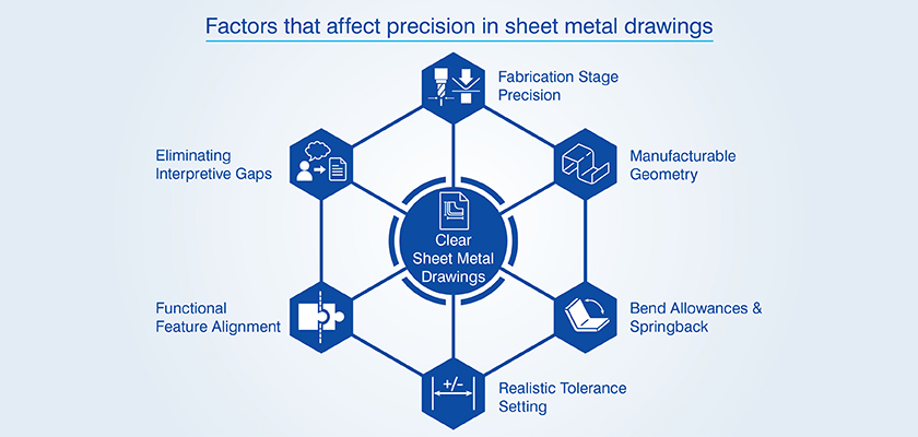
Getting precision right in your sheet metal drawings requires you to balance the complex relationship between geometry, materials and the production process. This interplay is what determines whether your finished parts actually match your design in the first place.
- Precision at different stages of fabrication: If you’re cutting your metal, you need to think about tight tolerances for your profiles. But if you’re bending it, you need to get the allowances right and making considerations for springback.
- Manufacturable geometry requirements: You need to factor in the real world limits that can affect your materials like how thick they actually are, the grain direction and how they behave when they’re bent.
- Bend allowances and springback: Your K factors and how you compensate for the way the material springs back after being bent need to be tuned to match up with what the material actually does.
- Realistic tolerance setting: You need to set your base tolerances based on the real world forming limitations.
- Functional feature alignment: No matter what sequence your manufacturing process follows, your dimensional schemes need to keep the critical features in the right geometric relationship.
- Eliminating interpretive gaps: Make sure your specs are complete and clear so that there is no confusion.
Get precise 2D and 3D sheet-metal drafts ready for fabrication.
Request Drafting »Top 6 tips for precise and clean sheet metal drawings
Here are some real world techniques that will help you avoid fabrication errors and pitfalls which tend to slow down your workflow.
Tip 1: Structure sheet metal drawings for maximum readability
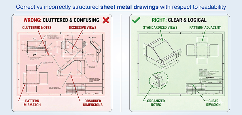
Using a standardized fabrication drafting makes it much easier for your fabrication team to follow your instructions and avoid confusion. So keep things simple, uncluttered and logical.
Choose views communicating geometry clearly
Your primary views should give a clear idea of the form you want. That means using logical projections that make your fabricators understand easily. Don’t clutter up the drawing with lots of section views unless you really need to show some internal features.
Organize elements for fast understanding
Don’t crowd your drawing with notes and details all over the place. Keep the general notes separate from the dimensions and the callouts for specific features. And don’t forget to use revision clouds to show up any changes, without covering up the dimensions that matter.
Tip 2: Apply dimensioning techniques that improve accuracy
By dimensioning to virtual intersection points you can avoid the problems that come with bent parts that are not right. And when you make your bend angles explicit they will be easier to measure when you are setting up.
Use baseline and ordinate dimensions
These types of dimensioning schemes are easier for CNC machines to deal with than chain dimensions, which can add up errors. And with a single datum that ties all your features to one reference point, you avoid building up cumulative tolerances.
Eliminate over dimensioning
Having too many dimensions can cause conflicts and that requires fabricators to take tough calls about which one takes precedence. This causes inconsistency and variation. So make sure you are only including what you really need.
Tip 3: Specify bend information clearly for error free forming
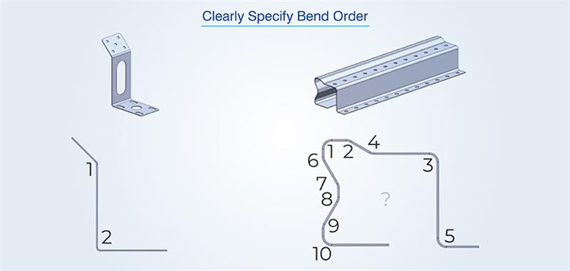
Complete bend specs removes the scope for any assumptions and this helps you avoid forming errors. Every bend needs its angle, radius, direction and location clearly spelled out. Make sure you’re aligning bend radii with the thickness of the material so you don’t get cracking. Also mark the grain direction in materials that behave differently depending on the way they’re laid out.
Document allowances and deductions accurately
CAD conversion of 3D geometry into flat patterns depends on being spot on with bend allowances. You need to make sure you document the following bend allowance details:
- K factors based on material grade, temper and thickness combinations.
- Springback compensation values based on how hard the material is and what bend angles you need.
- Bend deductions that take into account the tooling radius and how the material will behave under stress.
You need to carefully consider both springback and material variability. When sheet metal detailed drawings ignore all this, operators try to make adjustments on the fly and this wastes time and material. That’s why understanding the benefits of sheet metal drawings is crucial for accurate and efficient production.
Use clear bend direction indicators
Standardize symbols so that everyone is updated. Up bends and down bends need to be clear and the flat pattern needs to be orientated correctly. Make sure you’re using different symbols consistently across all sheet metal part drawings.
To get bend direction right, you need to consider the following:
- Use standardized arrow symbols to show whether it’s an up bend or a down bend and make it clear relative to the flat pattern reference plane.
- Number the bends in sequence, especially where you’ve got multiple bends that need to be done in a specific order.
- Use view orientation markers to show which surface the operator needs to be looking at during each forming operation.
If you have any special notes for hemming, offset bends or non standard operations, make sure to add those as well.
Tip 4: Prepare flat patterns that ensure cutting and forming accuracy
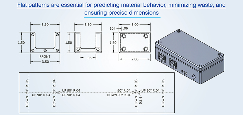
Flat pattern accuracy makes sure cut blanks actually fold into the right dimensions. You catch potential problems way early by checking your patterns thoroughly before production.
Clean and validate DXF files
Don’t share DXF files with any extra information that can confuse the CNC machines. Include just the profile geometry without any annotations. That can hinder you cutting job and hit parsing errors with CNC interpreters trying to process them.
Following table lists such common issues and how you can avoid them:
| Issue type | Fabrication impact | Prevention method |
|---|---|---|
| Open contours | Failed nesting, incomplete cuts | Make sure you check end points before exporting |
| Duplicate geometry | Redundant tool passes, timing errors | Use CAD software to run a geometry cleanup command |
| Annotation elements | Parser errors, unwanted cuts | Export the profile layers without any text or dimensions |
| Overlapping lines | Kerf compensation failures | Validate that all of your profiles are single lines |
For K factors make sure you are using real world data for how the material behaves rather than relying on default settings of your software. Tooling choices must also align with what you have got access to in the shop.
Tip 5: Communicate material and hardware details with clarity
If you have all the necessary details, you can avoid wrong stock getting ordered. For materials, include the grade, thickness, what tolerance is acceptable and who your supplier is. And also document every last detail of hardware installation.
Write material callouts eliminating ambiguity
When you’re ordering materials, make sure to include the temper, how it’s finished, what the coating specifications are and what standards apply. For example your callout should read “Aluminum 6061 T6, Mill Finish, per ASTM B209”.
Detail hardware requirements precisely
With hardware you need to specify exactly what type of fastener you want, how big it is, what it’s made of, what finish it has and how tight it should be installed. Hole tables need to clearly tie into the actual hardware you’re calling out. You also need to get the orientation right or you’ll end up with it all put together wrong.
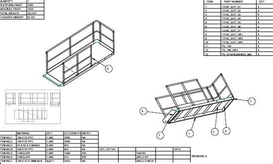
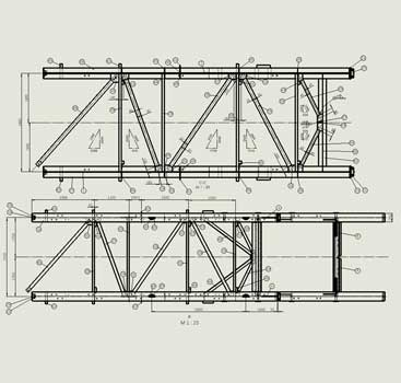
3D Models & 2D Drawings for Walkway and Hoppers
An Irish manufacturing firm, designing and installing recycling plant equipment, had a large number of fragmented CAD files (STEP) that required 3D models and 2D drawings of the walkways & hoppers to be produced reliably.
TrueCADD turned the STEP files into detailed 3D models and 2D drawings of the walkways, railings, handrails and hopper assemblies. The fabrication ready details we added ensured all the detail drawings would line up with the original engineering specifications.
The end result was:
- Fabrication ready 2D drawings and 3D CAD models
- Production accuracy improved & rework reduced
- Support for seamless assembly of the plant during installation
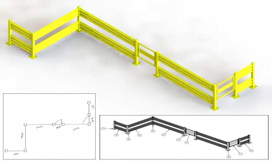 Gaurdrail 2D Drawings and 3D Model
 Handrail CAD Drawings
Tip 6: Use CAD tools effectively to improve drawing consistency
You are able to automate standards and parametric relationships using CAD today. The modern CAD platform can help identify errors and inconsistencies in your design before your fabrication team sees them.
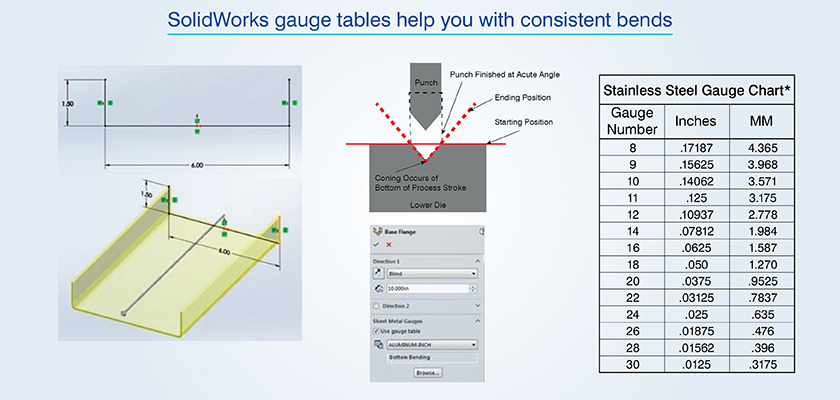
- Utilize gauge tables for bend consistency: Within SolidWorks sheet metal environments, you may utilize a gauge table to ensure that your bend allowance is consistent. A gauge table ties together the relationship between material thickness to bend radius and K factor. Using SolidWorks for sheet metal drafting allows designers to apply these gauge tables effectively, ensuring accurate and consistent part fabrication.
- Automate material callout propagation: Using Autodesk Inventor’s iProperties system you can also automate title block population and revision tracking within your fabrication drafting output. Simply enter in the material specifications once and they will be automatically propagated throughout your drawing sheets, BOMs and flat pattern views.
- Synchronizing revisions: Using AutoCAD’s Sheet Set Manager, you can keep all of your sheet metal part drawings synchronized under the same project as the current revisions.
- Configure clean DXF exports: When you’re exporting DXF files from Autodesk Inventor, you can configure layer mapping to get cutting profiles and annotations separately. This way, CNC programmers get files with profiles on designated layers and dimensions excluded with no more manual cleanup needed.
How to maintain sheet metal drawing precision and Clarity?
When you catch errors before drawings get sent to production, the quality of them keeps getting better with every release. This promotes clarity in shared understanding and helps get drawings ready to go.
Review processes to maintain sheet metal drawing precision and clarity:
- Structured review using a checklist: Make sure you’re looking at all the crucial elements every time you review a drawing before it goes out.
- Cross functional checks: Get the fabrication, machining and QA teams involved. They can spot potential problems that might come up in different phases of production.
- DXF file and flat pattern validation: Make sure that what you are exporting is clean and simple and can be read by a CNC machine. Also make sure that the flat pattern is going to unfold accurately.
- Annotation and tolerance checks: Make sure all the information needed with your drawing is clearly included and the tolerances that you have called out are practical and feasible.
- Strict revision control: Always keep track of changes in the draft with a proper version control in place.
- Manufacturer collaboration: Get feedback from the people who are actually working with your drawings and use what they say to keep improving their quality.
Reduce rework with flawlessly prepared CAD drawing sets.
Talk to experts »SolidWorks 3D Modeling for Structural Metal Products
A Russian steel structure company was struggling with their monthly deliverables. The 2D PDFs and BOMs they worked with had limited design clarity and affected fabrication workflow efficiency.
TrueCADD turned the client’s 2D inputs into SolidWorks 3D models, complete with fully assembled parts and fabrication ready drawings. The engineering team made sure the geometry was spot on, the materials were accurately interpreted and all the detailing was right for efficient production.
The final deliverables were:
- 3D models, assemblies detailed part drawings all built in SolidWorks
- STEP, DXF and PDF files for all components
- Boost in drawing development
 Metal Parts CAD Drawings in SolidWorks
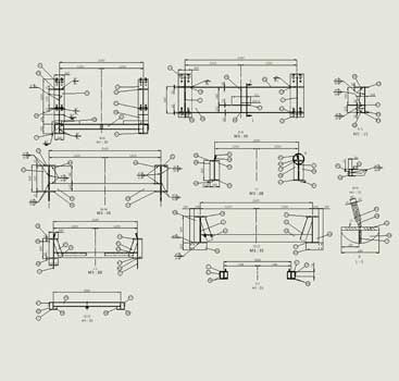 Metal Parts Assembly Drawings
Conclusion
Precision and clarity in sheet metal drawings can be ensured only by paying attention to the detailed fabrication of parts. When you take the time to develop sheet metal designs based on real-world conditions (i.e., material behavior and tooling limitations) you will minimize the number of delays and quality control problems caused by incorrect interpretation.
Accurate dimensioning, correct inclusion of all bend specifications, complete flat pattern and material callout information provide a solid base for confident part completion. As these become standardized, you will be able to realize significant reductions in rework, faster quote times, reduced scrap levels and higher percentages of first time right production at high quality levels.
Speed up CNC cutting with perfectly prepared DXF files.
Contact us »
Harika Singh
Harika Singh is a published author with over 20 years of experience working with leading organizations in India and the United States. She develops authoritative content on BIM, CAD, VDC, digital engineering, and construction technology. Her expertise lies in translating complex technical concepts into actionable insights that help AEC professionals improve collaboration, efficiency, and project outcomes.
Related Posts

Need help on an ongoing basis?
We establish long term business relationships with clients and are committed to total customer satisfaction.
Home |
Sitemap |
Privacy Policy | Data Security & Confidentiality |
Contact us |
![]()